Difference between revisions of "120 GHz Transceivers"
(→FAQ: TRX_120_00*) |
|||
| (20 intermediate revisions by 4 users not shown) | |||
| Line 1: | Line 1: | ||
__NUMBEREDHEADINGS__ | __NUMBEREDHEADINGS__ | ||
| − | + | <div style="overflow-x: auto"> | |
| − | {| style="text-align:center; width: | + | {| style="text-align:center; width:100%" |
| − | |style="background-color:#f2f2f2"|<span style="color: black">'''Front End'''</span> | + | |style="width: 14%; background-color:#f2f2f2"|<span style="color: black">'''Front End'''</span> |
| − | |style="background-color:#f2f2f2"|<span style="color: black">'''Status of IC'''</span> | + | |style="width: 14%; background-color:#f2f2f2"|<span style="color: black">'''Status of IC'''</span> |
| − | |style="background-color:#f2f2f2"|<span style="color: black">'''Package'''</span> | + | |style="width: 15%; background-color:#f2f2f2"|<span style="color: black">'''Package'''</span> |
| − | |style="background-color:#f2f2f2"|<span style="color: black">'''Antenna Solutions'''</span> | + | |style="width: 15%; min-width:130px; background-color:#f2f2f2"|<span style="color: black">'''Antenna Solutions'''</span> |
| − | |style="background-color:#f2f2f2"|<span style="color: black">'''Evaluation / Sensor'''</span> | + | |style="width: 14%; min-width:130px; background-color:#f2f2f2"|<span style="color: black">'''Evaluation / Sensor'''</span> |
| + | |style="width: 28%; min-width:250px; background-color:#f2f2f2"|<span style="color: black">'''Typical Applications'''</span> | ||
|- | |- | ||
|style="text-align: left; padding-left: 1%; padding-right: 1%; vertical-align: top"| | |style="text-align: left; padding-left: 1%; padding-right: 1%; vertical-align: top"| | ||
Single Channel Transceiver | Single Channel Transceiver | ||
| − | *[https://siliconradar.com/datasheets/ | + | *[https://siliconradar.com/datasheets/Datasheet_TRX_120_001.html TRX_120_001] |
|style="text-align: left; padding-left: 1%; padding-right: 1%; vertical-align: top"| | |style="text-align: left; padding-left: 1%; padding-right: 1%; vertical-align: top"| | ||
*Series production | *Series production | ||
| Line 16: | Line 17: | ||
*[[(FAM) QFN#Film Assisted Molded (FAM) QFN|FAM QFN]] | *[[(FAM) QFN#Film Assisted Molded (FAM) QFN|FAM QFN]] | ||
|style="text-align: left; padding-left: 1%; padding-right: 1%; vertical-align: top"| | |style="text-align: left; padding-left: 1%; padding-right: 1%; vertical-align: top"| | ||
| − | *Antenna | + | *[[Antennas#Antenna on Package|Antenna on Package]] |
| − | |||
|style="text-align: left; padding-left: 1%; padding-right: 1%; vertical-align: top"| | |style="text-align: left; padding-left: 1%; padding-right: 1%; vertical-align: top"| | ||
[https://siliconradar.com/wiki/Evalkits SiRad Easy®]</br> | [https://siliconradar.com/wiki/Evalkits SiRad Easy®]</br> | ||
[https://siliconradar.com/wiki/Evalkits SiRad Simple®] | [https://siliconradar.com/wiki/Evalkits SiRad Simple®] | ||
| + | |style="text-align: left; padding-left: 1%; padding-right: 1%; vertical-align: top"| | ||
| + | [[Distance, Level, Position|Range Finding]], [[Distance, Level, Position|Interface Measurement]],</br> | ||
| + | [[Distance, Level, Position|Level Probing]], [[Distance, Level, Position|Position Finding]],</br> | ||
| + | [[Distance, Level, Position|Presence Detection]], [[Motion, Speed, Vibration|Speed Measurement]],</br> | ||
| + | [[Motion, Speed, Vibration|Vibration Detection]], [[Material Analysis|Non-destructive Testing]],</br> | ||
| + | [[Material Analysis|Positioning]], [[Material Analysis|Surface Profiling]],</br> | ||
| + | [[Life Form Analysis|Vital Sign Detection]]</br> | ||
|- | |- | ||
|style="text-align: left; padding-left: 1%; padding-right: 1%; vertical-align: top; background-color:#f2f2f2"| | |style="text-align: left; padding-left: 1%; padding-right: 1%; vertical-align: top; background-color:#f2f2f2"| | ||
Single Channel Transceiver | Single Channel Transceiver | ||
| − | *[https://siliconradar.com/datasheets/ | + | *[https://siliconradar.com/datasheets/Datasheet_TRA_120_002.html TRA_120_002] |
|style="text-align: left; padding-left: 1%; padding-right: 1%; vertical-align: top; background-color:#f2f2f2"| | |style="text-align: left; padding-left: 1%; padding-right: 1%; vertical-align: top; background-color:#f2f2f2"| | ||
*Series production | *Series production | ||
| Line 30: | Line 37: | ||
*[[(FAM) QFN|QFN]] | *[[(FAM) QFN|QFN]] | ||
|style="text-align: left; padding-left: 1%; padding-right: 1%; vertical-align: top; background-color:#f2f2f2"| | |style="text-align: left; padding-left: 1%; padding-right: 1%; vertical-align: top; background-color:#f2f2f2"| | ||
| − | *Antenna | + | *[[Antennas#Antenna on Chip|Antenna on Chip]] (5) |
|style="text-align: left; padding-left: 1%; padding-right: 1%; vertical-align: top; background-color:#f2f2f2"| | |style="text-align: left; padding-left: 1%; padding-right: 1%; vertical-align: top; background-color:#f2f2f2"| | ||
[https://siliconradar.com/wiki/Evalkits SiRad Easy®]</br> | [https://siliconradar.com/wiki/Evalkits SiRad Easy®]</br> | ||
[https://siliconradar.com/wiki/Evalkits SiRad Simple®] | [https://siliconradar.com/wiki/Evalkits SiRad Simple®] | ||
| + | |style="text-align: left; padding-left: 1%; padding-right: 1%; vertical-align: top; background-color:#f2f2f2"| | ||
| + | [[Distance, Level, Position|Range Finding]], [[Distance, Level, Position|Level Probing]],</br> | ||
| + | [[Distance, Level, Position|Position Finding]], [[Distance, Level, Position|Presence Detection]],</br> | ||
| + | [[Motion, Speed, Vibration|Speed Measurement]], [[Motion, Speed, Vibration|Vibration Detection]],</br> | ||
| + | [[Material Analysis|Non-destructive Testing]], [[Material Analysis|Positioning]],</br> | ||
| + | [[Life Form Analysis|Vital Sign Detection]]</br> | ||
|- | |- | ||
|style="text-align: left; padding-left: 1%; padding-right: 1%; vertical-align: top"| | |style="text-align: left; padding-left: 1%; padding-right: 1%; vertical-align: top"| | ||
| Line 45: | Line 58: | ||
*[[(FAM) QFN|QFN]] | *[[(FAM) QFN|QFN]] | ||
|style="text-align: left; padding-left: 1%; padding-right: 1%; vertical-align: top"| | |style="text-align: left; padding-left: 1%; padding-right: 1%; vertical-align: top"| | ||
| − | *Antenna | + | *[[Antennas#Antenna on Chip|Antenna on Chip]] (5) |
|style="text-align: left; padding-left: 1%; padding-right: 1%; vertical-align: top"| | |style="text-align: left; padding-left: 1%; padding-right: 1%; vertical-align: top"| | ||
[https://siliconradar.com/wiki/Evalkits SiRad Easy®] | [https://siliconradar.com/wiki/Evalkits SiRad Easy®] | ||
| + | |style="text-align: left; padding-left: 1%; padding-right: 1%; vertical-align: top"| | ||
| + | [[Distance, Level, Position|Pressure Measurement]], [[Distance, Level, Position|Temperature Measurement]],</br> | ||
| + | [[Material Analysis|Non-destructive Testing]], [[Material Analysis|Positioning]],</br> | ||
| + | [[Material Analysis|Surface Profiling]], [[Material Analysis|Thickness Measurement]] | ||
|- | |- | ||
|style="text-align: left; padding-left: 1%; padding-right: 1%; vertical-align: top; background-color:#f2f2f2"| | |style="text-align: left; padding-left: 1%; padding-right: 1%; vertical-align: top; background-color:#f2f2f2"| | ||
| Line 54: | Line 71: | ||
|style="text-align: left; padding-left: 1%; padding-right: 1%; vertical-align: top; background-color:#f2f2f2"| | |style="text-align: left; padding-left: 1%; padding-right: 1%; vertical-align: top; background-color:#f2f2f2"| | ||
*In development | *In development | ||
| − | *Inquire for schedule / availability | + | *Inquire for schedule/availability |
*TRL 4 | *TRL 4 | ||
|style="text-align: left; padding-left: 1%; padding-right: 1%; vertical-align: top; background-color:#f2f2f2"| | |style="text-align: left; padding-left: 1%; padding-right: 1%; vertical-align: top; background-color:#f2f2f2"| | ||
| − | *[[Bare Die Bonded to PCB]] ( | + | *[[Bare Die Bonded to PCB]] (6) |
| − | *[[Chip Embedding]] ( | + | *[[Chip Embedding]] (6) |
|style="text-align: left; padding-left: 1%; padding-right: 1%; vertical-align: top; background-color:#f2f2f2"| | |style="text-align: left; padding-left: 1%; padding-right: 1%; vertical-align: top; background-color:#f2f2f2"| | ||
| − | * | + | *[[Antennas#Antenna on PCB|Antenna on PCB]] |
| − | * | + | *[[Antennas#Antenna on Package|Antenna on Package]] (6) |
|style="text-align: left; padding-left: 1%; padding-right: 1%; vertical-align: top; background-color:#f2f2f2"| | |style="text-align: left; padding-left: 1%; padding-right: 1%; vertical-align: top; background-color:#f2f2f2"| | ||
| − | [https://siliconradar.com/wiki/Evalkits SiRad Easy®] ( | + | [https://siliconradar.com/wiki/Evalkits SiRad Easy®] (6) |
| + | |style="text-align: left; padding-left: 1%; padding-right: 1%; vertical-align: top; background-color:#f2f2f2"| | ||
| + | [[Motion, Speed, Vibration|Motion Detection]], [[Objects, Presence, Shape|Shape Detection]]</br> | ||
|} | |} | ||
| − | + | </div> | |
(1) Qualified after JEDEC; MSL</br> | (1) Qualified after JEDEC; MSL</br> | ||
(2) Under investigation</br> | (2) Under investigation</br> | ||
| Line 71: | Line 90: | ||
(4) Patented assembly solution</br> | (4) Patented assembly solution</br> | ||
(5) In silicon, completely moulded</br> | (5) In silicon, completely moulded</br> | ||
| + | (6) Under Development</br> | ||
__FORCETOC__ | __FORCETOC__ | ||
| − | + | = TRX_120_001 = | |
| − | = | + | {| |
| + | [[File:TRX_120GHz_wiki.jpg|border|right|220px|link={{filepath:{{PAGENAME:Media:TRX_120GHz_wiki.jpg}}}}]] | ||
| + | |} | ||
| − | The RFE is an integrated transceiver circuit for the 122-GHz ISM band with antennas in QFN 8x8 package. It includes a low-noise amplifier (LNA), quadrature mixers, a poly-phase filter, a voltage controlled oscillator, divide-by-32 outputs and transmit and receive antennas. The RF signal from the oscillator is directed to the RX path via buffer circuits. The RX signal is amplified by the LNA and converted to the baseband by two mixers with quadrature local oscillator (LO). The 120-GHz LO has four analog tuning inputs with different tuning ranges and tuning slopes. The tuning inputs can be combined to obtain a wide frequency tuning range. The analog tuning inputs together with integrated frequency divider and external fractional-N PLL can be used for frequency modulated continuous wave (FMCW) radar operation. With fixed oscillator frequency it can be used in continuous wave (CW) mode. Other modulation schemes are possible as well by utilizing analog tuning inputs. The IC is fabricated in SG13S SiGe BiCMOS technology [https://www.ihp-microelectronics.com/en/services/mpw-prototyping/sigec-bicmos-technologies.html]. | + | The RFE is an integrated transceiver circuit for the 122-GHz ISM band with antennas in the QFN 8x8 package. It includes a low-noise amplifier (LNA), quadrature mixers, a poly-phase filter, a voltage controlled oscillator, divide-by-32 outputs, and transmit and receive antennas. The RF signal from the oscillator is directed to the RX path via buffer circuits. The RX signal is amplified by the LNA and converted to the baseband by two mixers with a quadrature local oscillator (LO). The 120-GHz LO has four analog tuning inputs with different tuning ranges and tuning slopes. The tuning inputs can be combined to obtain a wide frequency tuning range. The analog tuning inputs together with integrated frequency divider and external fractional-N PLL can be used for frequency modulated continuous wave (FMCW) radar operation. With fixed oscillator frequency it can be used in continuous wave (CW) mode. Other modulation schemes are possible as well by utilizing analog tuning inputs. The IC is fabricated in SG13S SiGe BiCMOS technology [https://www.ihp-microelectronics.com/en/services/mpw-prototyping/sigec-bicmos-technologies.html]. |
| − | The main application field of the 120-GHz transceiver radar frontend is in short range radar systems with a range up to some 10 meters. By using dielectric lenses, the range can be increased considerably. The RFE can be used in FMCW mode as well as in CW mode. Although the chip is intended for use in the ISM band 122 GHz - 123 GHz, it is also possible to extend the bandwidth to the full tuning range of 7 GHz. | + | The main application field of the 120-GHz transceiver radar frontend is in short-range radar systems with a range up to some 10 meters. By using dielectric lenses, the range can be increased considerably. The RFE can be used in FMCW mode as well as in CW mode. Although the chip is intended for use in the ISM band 122 GHz - 123 GHz, it is also possible to extend the bandwidth to the full tuning range of 7 GHz. |
= TRX_120_002 = | = TRX_120_002 = | ||
| − | The radar-front end (RFE) is an integrated transceiver circuit for the 120 GHz ISM band with antennas on chip in a QFN 5x5 package. It includes a low-noise amplifier (LNA), quadrature mixers, poly-phase filter, voltage controlled oscillator with digital band switching, divide-by-32 outputs, and transmit and receive antennas. The RF-signal from oscillator is directed to RX path via buffer circuits. The RX signal is amplified by | + | The radar-front end (RFE) is an integrated transceiver circuit for the 120 GHz ISM band with antennas on-chip in a QFN 5x5 package. It includes a low-noise amplifier (LNA), quadrature mixers, poly-phase filter, voltage controlled oscillator with digital band switching, divide-by-32 outputs, and transmit and receive antennas. The RF-signal from the oscillator is directed to the RX path via buffer circuits. The RX signal is amplified by an LNA and converted to baseband in two mixers with quadrature LO. The 120 GHz oscillator has three analog coarse tuning inputs and one analog fine-tuning input. The tuning inputs can be combined to obtain a large tuning range and large bandwidth. The analog tuning inputs together with integrated frequency divider and external fractional-N PLL can be used for frequency modulated continuous wave (FMCW) radar operation. With fixed oscillator frequency it can be used in continuous wave (CW) mode. Other modulation schemes are possible as well by utilizing analog tuning inputs. The IC is fabricated in IHP SG13S SiGe BiCMOS technology [https://www.ihp-microelectronics.com/en/services/mpw-prototyping/sigec-bicmos-technologies.html]. |
| − | + | The main application field of the 120 GHz transceiver RFE is in short-range radar systems. With the use of dielectric lenses, the range can be increased considerably. The RFE can be used in FMCW mode as well in CW-mode. Although the chip is intended for use in ISM band 122 GHz - 123 GHz, it is also possible to extend the bandwidth to the full tuning range of almost 7 GHz. | |
= FAQ: TRX_120_00* = | = FAQ: TRX_120_00* = | ||
| − | + | Please see [[FAQs]] page for frequently asked questions and TRA_120_002 SiRad front end datasheet [https://siliconradar.com/datasheets/Datasheet_TRA_120_002.html]. | |
| − | |||
| − | |||
| − | |||
| − | |||
| − | |||
| − | |||
| − | : | ||
| − | |||
| − | |||
| − | |||
| − | |||
| − | |||
| − | |||
| − | |||
| − | |||
| − | |||
| − | |||
| − | |||
| − | |||
| − | |||
| − | |||
| − | |||
| − | |||
| − | |||
| − | |||
| − | |||
| − | |||
| − | |||
| − | |||
| − | |||
| − | |||
| − | |||
| − | |||
| − | |||
Latest revision as of 07:48, 23 March 2021
| Front End | Status of IC | Package | Antenna Solutions | Evaluation / Sensor | Typical Applications |
|
Single Channel Transceiver |
|
Range Finding, Interface Measurement, | |||
|
Single Channel Transceiver |
|
|
Range Finding, Level Probing, | ||
|
Ultra Wideband Single Channel Transceiver
|
|
|
Pressure Measurement, Temperature Measurement, | ||
|
Multi Channel Transceiver
|
|
|
SiRad Easy® (6) |
(1) Qualified after JEDEC; MSL
(2) Under investigation
(3) Incl. lens (Si / 3D-printed)
(4) Patented assembly solution
(5) In silicon, completely moulded
(6) Under Development
Contents
1 TRX_120_001
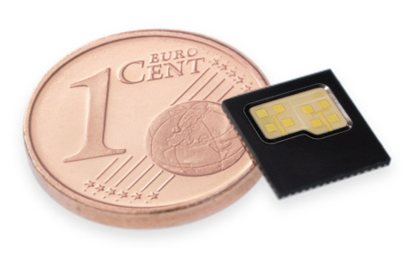
The RFE is an integrated transceiver circuit for the 122-GHz ISM band with antennas in the QFN 8x8 package. It includes a low-noise amplifier (LNA), quadrature mixers, a poly-phase filter, a voltage controlled oscillator, divide-by-32 outputs, and transmit and receive antennas. The RF signal from the oscillator is directed to the RX path via buffer circuits. The RX signal is amplified by the LNA and converted to the baseband by two mixers with a quadrature local oscillator (LO). The 120-GHz LO has four analog tuning inputs with different tuning ranges and tuning slopes. The tuning inputs can be combined to obtain a wide frequency tuning range. The analog tuning inputs together with integrated frequency divider and external fractional-N PLL can be used for frequency modulated continuous wave (FMCW) radar operation. With fixed oscillator frequency it can be used in continuous wave (CW) mode. Other modulation schemes are possible as well by utilizing analog tuning inputs. The IC is fabricated in SG13S SiGe BiCMOS technology [1].
The main application field of the 120-GHz transceiver radar frontend is in short-range radar systems with a range up to some 10 meters. By using dielectric lenses, the range can be increased considerably. The RFE can be used in FMCW mode as well as in CW mode. Although the chip is intended for use in the ISM band 122 GHz - 123 GHz, it is also possible to extend the bandwidth to the full tuning range of 7 GHz.
2 TRX_120_002
The radar-front end (RFE) is an integrated transceiver circuit for the 120 GHz ISM band with antennas on-chip in a QFN 5x5 package. It includes a low-noise amplifier (LNA), quadrature mixers, poly-phase filter, voltage controlled oscillator with digital band switching, divide-by-32 outputs, and transmit and receive antennas. The RF-signal from the oscillator is directed to the RX path via buffer circuits. The RX signal is amplified by an LNA and converted to baseband in two mixers with quadrature LO. The 120 GHz oscillator has three analog coarse tuning inputs and one analog fine-tuning input. The tuning inputs can be combined to obtain a large tuning range and large bandwidth. The analog tuning inputs together with integrated frequency divider and external fractional-N PLL can be used for frequency modulated continuous wave (FMCW) radar operation. With fixed oscillator frequency it can be used in continuous wave (CW) mode. Other modulation schemes are possible as well by utilizing analog tuning inputs. The IC is fabricated in IHP SG13S SiGe BiCMOS technology [2].
The main application field of the 120 GHz transceiver RFE is in short-range radar systems. With the use of dielectric lenses, the range can be increased considerably. The RFE can be used in FMCW mode as well in CW-mode. Although the chip is intended for use in ISM band 122 GHz - 123 GHz, it is also possible to extend the bandwidth to the full tuning range of almost 7 GHz.
3 FAQ: TRX_120_00*
Please see FAQs page for frequently asked questions and TRA_120_002 SiRad front end datasheet [3].