Radar Sensor Modules
Contents
1 Reference Designs
1.1 General Information
Radar sensors can be designed with or without using a PLL (Phased Locked Loop). We developed our Radar evaluation kits with a PLL based design. The schematics of these designs are available to customers in Customer Download Area. The designs include front end control, baseband, analog to digital conversion, digital signal processing option, and data interfaces (control lines, UART, WiFi). There are no HF parts in the designs even though our front ends work with very high frequencies.
1.2 PLL based Design
A typical PLL based Radar sensor design consists of a front end chip, a PLL and loop filter, an amplifier and signal filter, an ADC, and optionally a digital signal processing unit and some data interfaces. While FPGAs and DSPs have been used widely for a long time for Radar processing, also micro-controllers and custom signal processors are used for that purpose today. Our designs include micro-controllers because they are cheap and quite flexible.
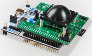
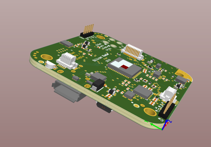
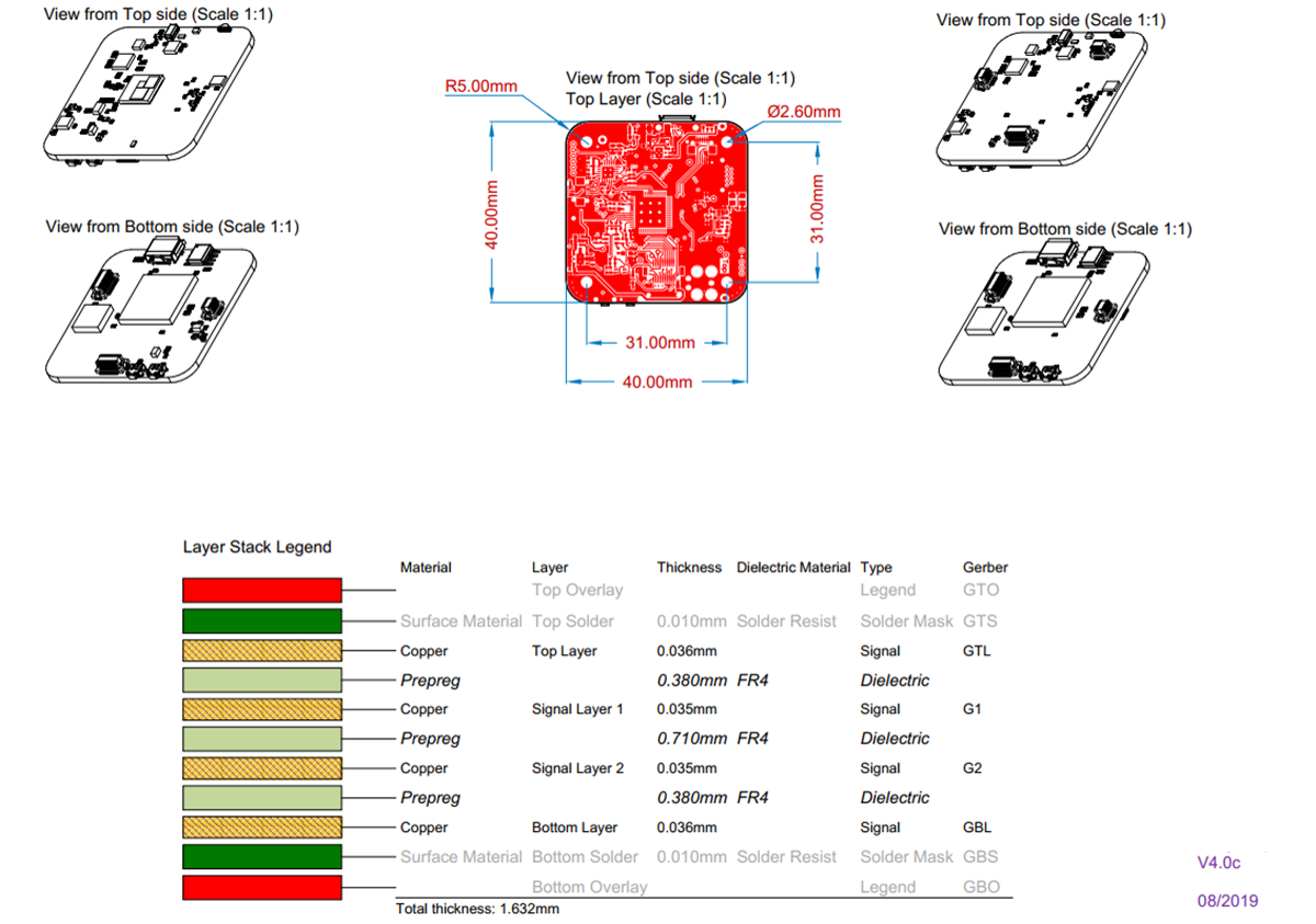
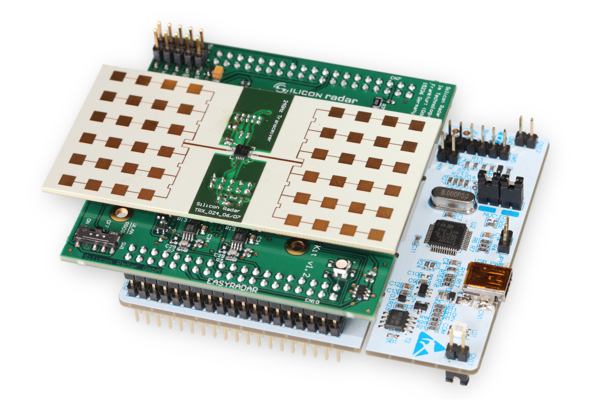
1.2.1 SiRad Easy
The SiRad Easy can mount our 24 GHz, 60 GHz, 120 GHz & 300 GHz front end boards. You can find more information about the Easy kit on the Evalkits info page on our website. We provide the SiRad Easy schematics in Customer Download Area along with our kit.
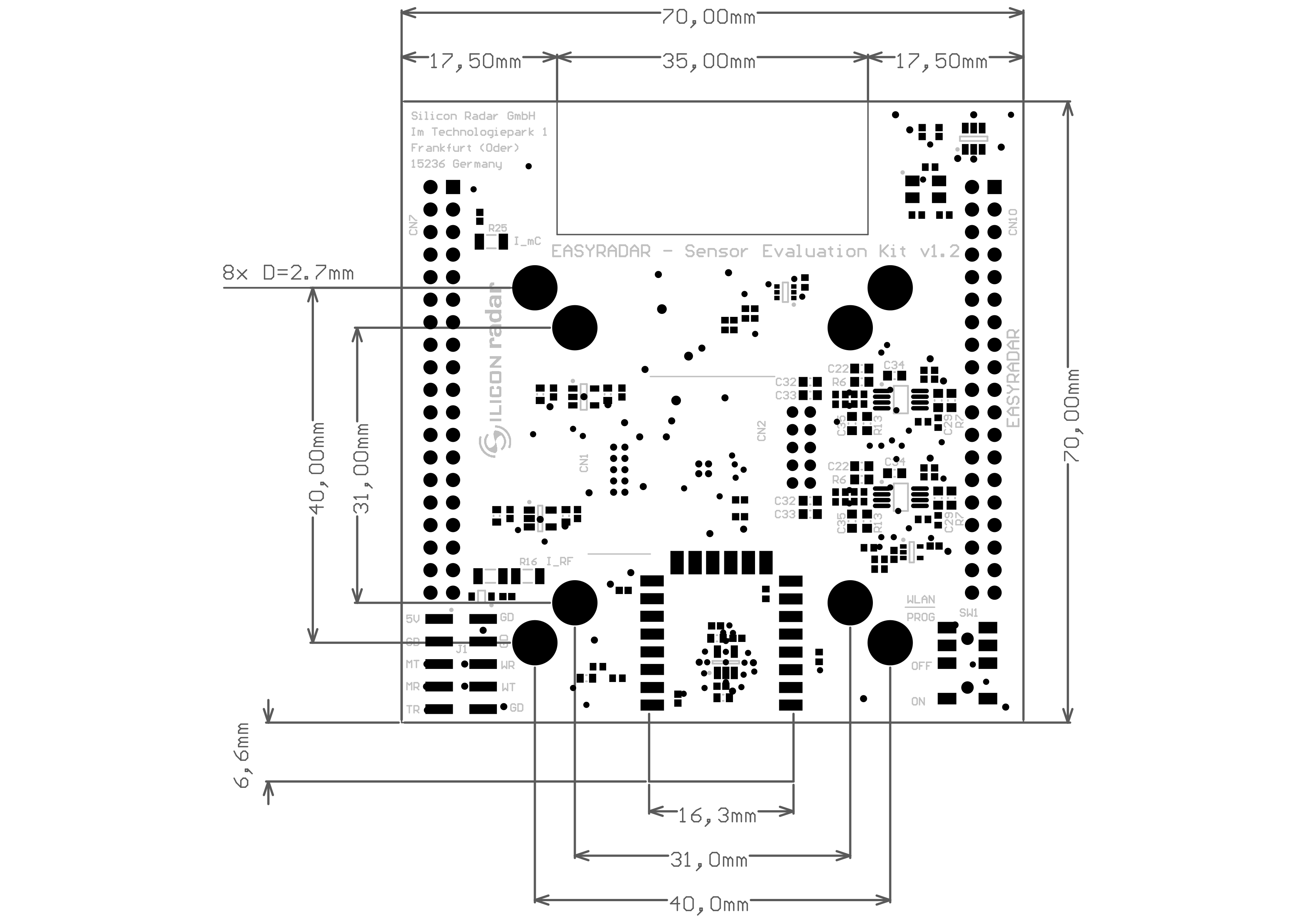
| SiRad Easy® with lens | Mechanical drawing of the SiRad Easy® Baseband Board |
|
|
1.2.2 SiRad Simple
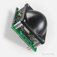
The SiRad Simple has a fixed 120 GHz front end but is smaller than the SiRad Easy. You can find more information about the Simple kit on the Evalkits info page on our website. We provide the SiRad Simple schematics in Customer Download Area along with our kit.
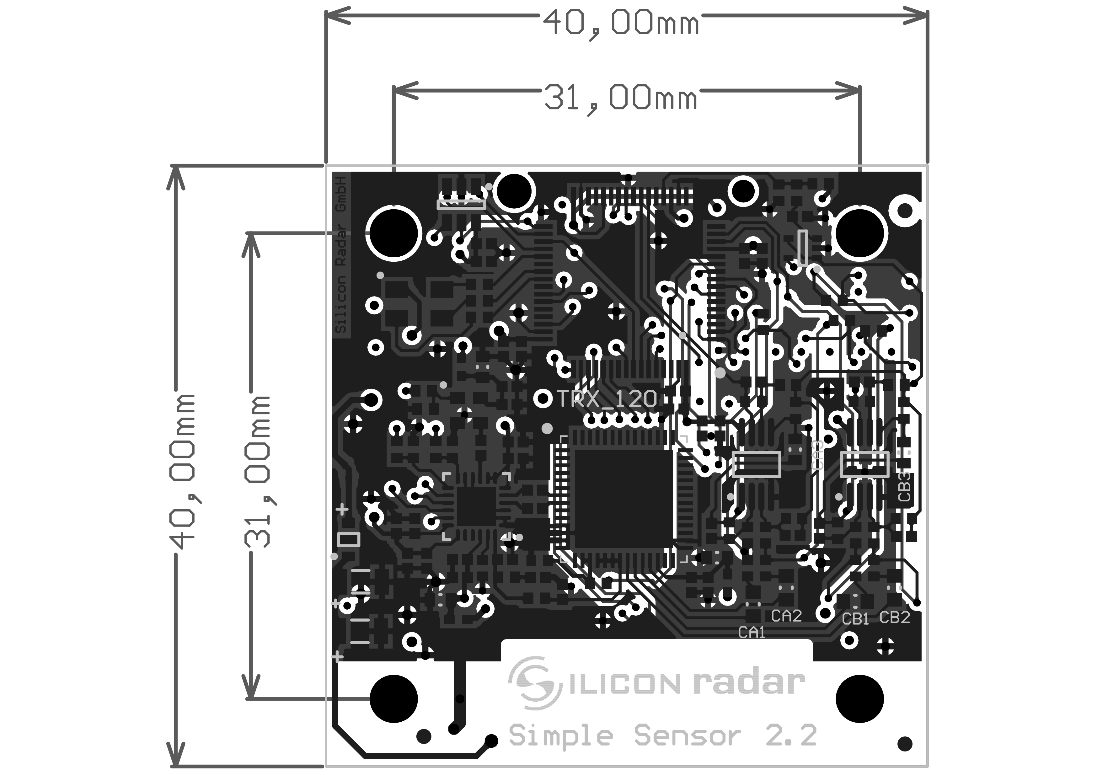
| SiRad Simple® with lens | Mechanical drawing of the SiRad Simple® |
|
|
2 Customized Sensor Design
2.1 General Information
Since the variety of possible applications for radar is huge, radar sensors need to be tuned specifically to the target application. Usually, the critical parameters are the update rate of the sensor, its resolution or the ability to separate targets, and its accuracy (of measured distance or speed). Mostly, the baseband needs to be designed specifically for the intended application and measurement principle, to match the desired parameters. Also, the signal processing software on the sensor needs to be implemented according to the needs of the application.
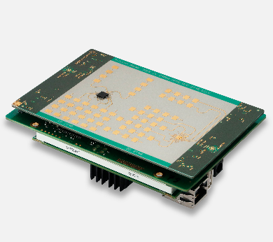
2.2 Radar Sensor Hardware
Our Reference Designs SiRad Easy® and SiRad Simple® can be used as a start point for sensor developments by our EvalKit customers. The schematics of the designs are available to our EvalKit customers in PDF form in Customer Download Area. The designs include front-end control, baseband, analog to digital conversion, digital signal processing option, and data interfaces (control lines, UART, WiFi). There are no HF parts in the designs even though our front ends work with very high frequencies.
| Customized sensor hardware, example | Customized sensor mechanical drawing, example |
|
|
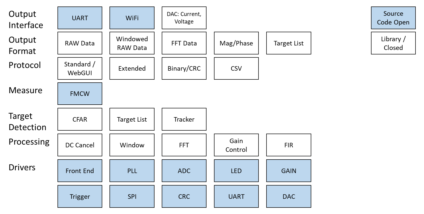
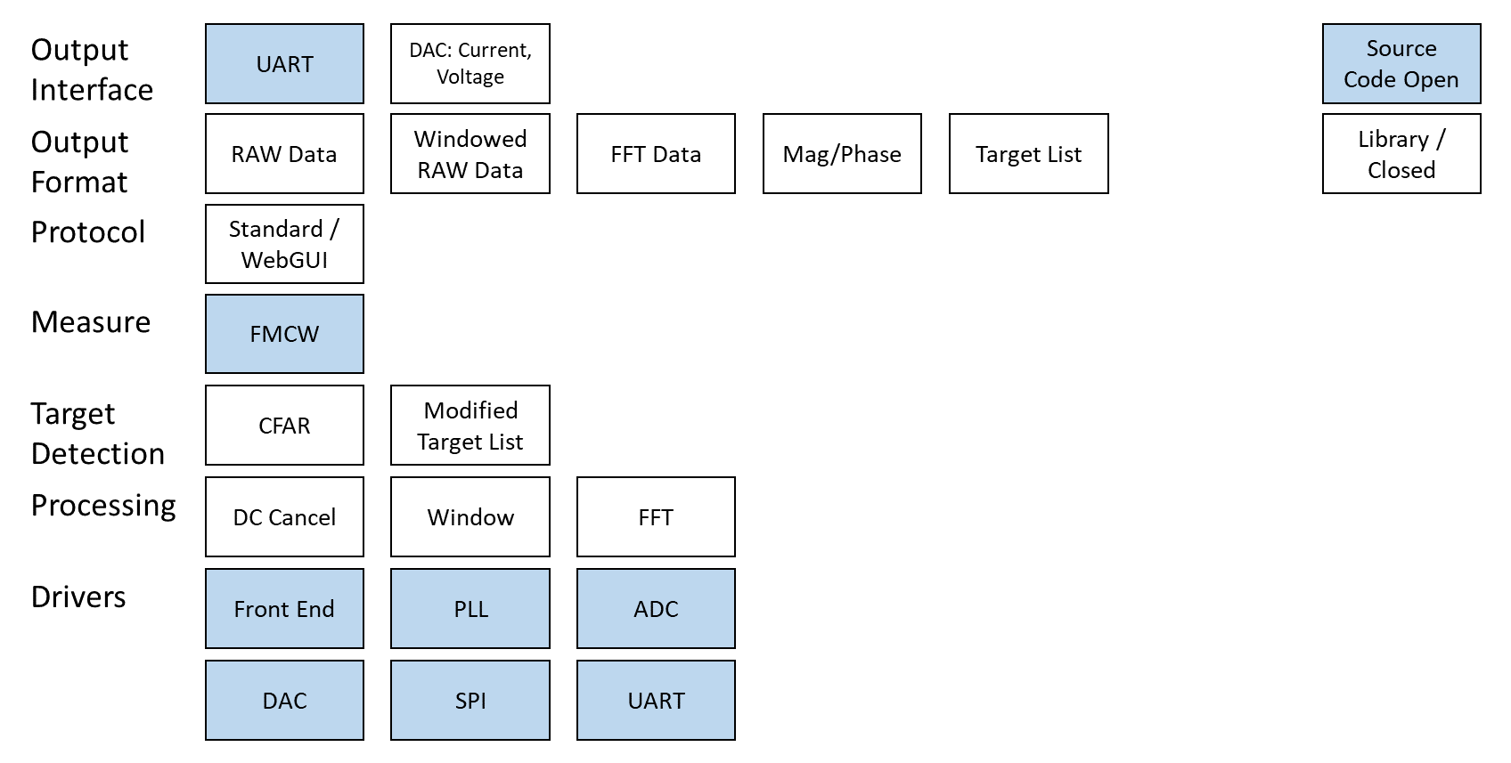
2.3 Radar Sensor Software
We also offer a free reference firmware implementation and signal processing library in our download area for our EvalKit customers. The firmware is written in embedded C and comes pre-flashed on our evaluation kits. The open firmware parts include drivers for front end control, baseband, PLL, and data interfaces (control lines, UART, WiFi). The library includes the signal processing functions that can be tried out with our evaluation kits. The reference firmware implementation and signal processing library can be used as a start point for sensor developments by our EvalKit customers.
| Embedded C firmware modules overview | Customized sensor software, example |
|
|
3 Radar Software
3.1 General Information
We offer different free software packages to our customers to try out our SiRad Easy® and SiRad Simple® evaluation kits and speed up custom sensor development. First, we offer a free reference firmware implementation and signal processing library. The firmware is written in embedded C and comes pre-flashed on our evaluation kits. Second, our browser-based WebGUI can connect to our evaluation kits and reference firmware to visualize live radar data. The GUI is written in HTML and JavaScript. Third, we also offer configuration scripts and examples to work with MATLAB & Octave and other third-party software. The mentioned software packages are available from our download area for our evaluation kit customers.
3.2 Evaluation Kit Firmware
The signal processing of our SiRad Easy® and SiRad Simple® evaluation kits is completely embedded in the microcontroller mounted on the kits. No further signal processing calculations are done in the WebGUI other than needed for displaying the data. You can find more information about the practical use of the firmware in the Evalkits section. This includes guidelines to tune the firmware to your application for update rate, resolution, and accuracy.
The reference firmware implementation and signal processing library are available in our download area for our EvalKit customers. The open firmware parts include drivers for front-end control, baseband, PLL, and data interfaces (control lines, UART, WiFi). The library includes the signal processing functions that can be tried out with our evaluation kits. The reference firmware implementation and signal processing library can be used as a start point for sensor developments by our EvalKit customers.
3.3 Evaluation Kit GUI
With the single-channel evaluation kits SiRad Easy® and SiRad Simple®, we provide our free and customizable WebGUI which is a browser-based GUI (for Microsoft Windows®), also see the picture below. From the WebGUI, you can visualize the radar data, change radar parameters such as base frequency, bandwidth, number of ramps, sampling frequency, FFT size, and more on the fly in the running system. Radar settings can be saved and re-used, up to 16 targets can be detected and are displayed in the WebGUI. For more information, also please visit WebGUI
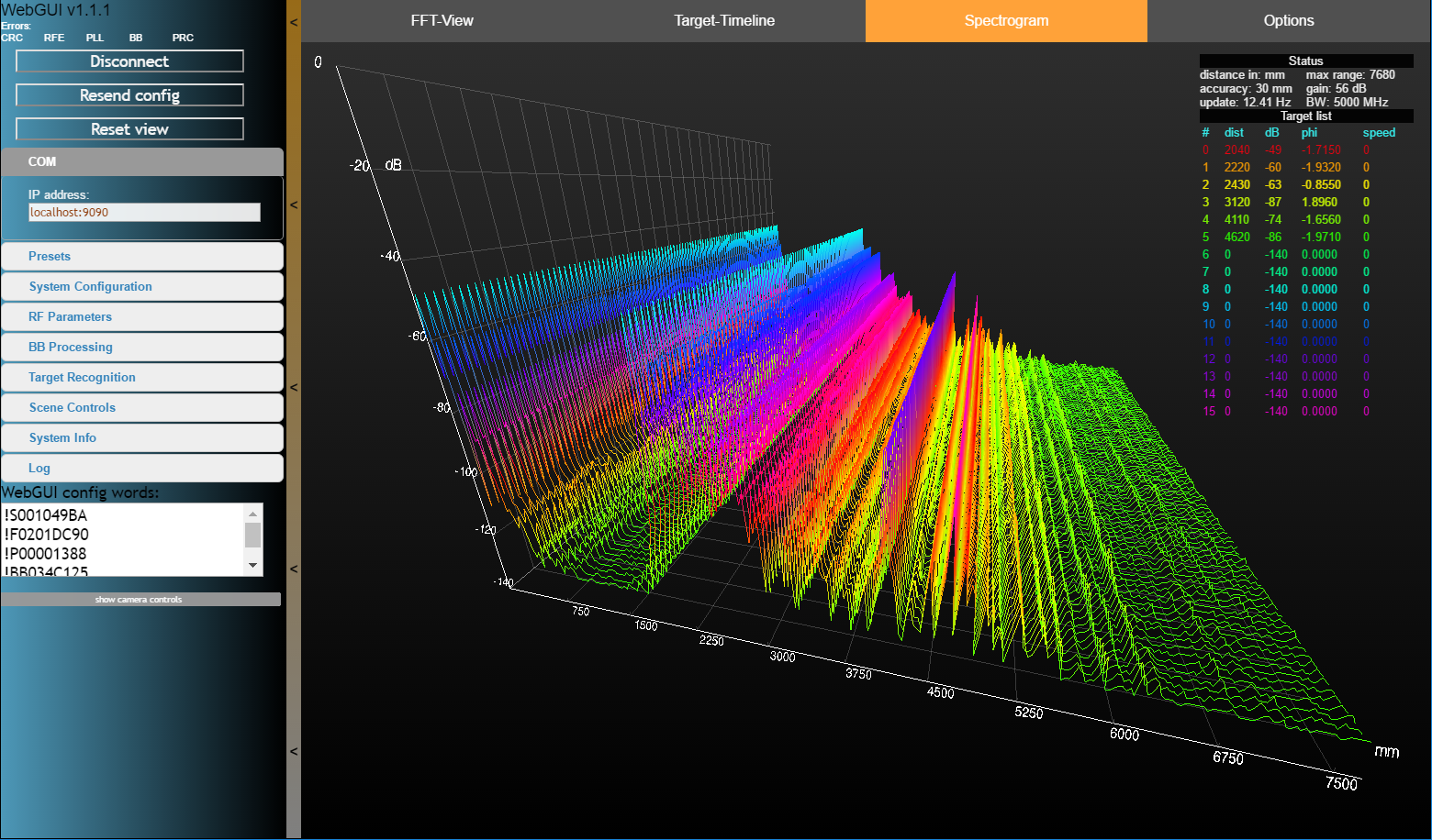
The Silicon Radar WebGUI consists of four main panels
- control panel on the left side for changing radar parameters,
- main menu on the top of the screen to change view modes with the active view in orange,
- scene/canvas itself where the sensor data is displayed,
- target list with the status fields on the right side of the screen (draggable).
Processing Parameters
- Sampling frequency
- Number of samples
- Number of ramps
- Downsampling
- FFT size
- Moving Averaging Filter
4 Antennas
4.1 General Information
The general rule of thumb:
- The higher the frequency the smaller the antenna.
- For the special case of patch antennas: The more antenna patches placed, the narrower the beamwidth.
- Connections from IC to antennas such as bond wires etc. cause impedance mismatch, decreasing efficiency, and bandwidth. This has to be matched again during antenna design. The smaller and less tolerant the structures, the easier the matching (for example an antenna on-chip is easier to match compared to an antenna on PCB).
4.2 External Antenna
Any external antenna that is commercially available, can be used for sensor designs using Silicon Radar ICs. The challenge of using such antennas is the transmission of the signal to the antenna from packaged IC, especially for very high frequencies. Therefore, it is generally common to use such antennas only for 24 GHz products.
Advantages:
- Various antenna types from various suppliers
- Commercially available, no special design required
Disadvantages:
- Hard to find for higher frequencies
- Transmission to the antenna has a high loss for higher frequencies, especially over the connectors
- Not suitable for high bandwidths
4.3 Antenna on PCB
Antennas can also be designed directly on a high-frequency PCB. RF-PCB materials are normally verified up to 110 GHz; however successful designs are also possible at 120 GHz ISM band.
Advantages:
- Flexible antenna designs are possible since the area is not limited as in the case of antenna on chip or on package
- Cheaper for prototyping compared to antennas on chip or on package
- Antennas can be placed very close to the IC on PCB, so transmission from IC to antenna can be efficient
- Suitable for 24 GHz and 60 GHz designs
Disadvantages:
- Long bond wires may limit the performance (depends also if bare IC is directly wire bonded to PCB or already in a package)
- Standard PCB technology is limited, also limiting the matching structures of antenna designs resulting in less efficiency at higher frequencies
- Standard PCB tolerances are high, increasing the center frequency shifts of final designs
- Not suitable for extremely high bandwidths
- RF-PCB material is expensive
4.4 Antenna in Package
Antennas can also be placed directly in high-frequency package. This increases the choice of materials and technologies (for example thin film) to design antennas. But in this case, the area may be limited, if compared to antennas on PCB. Successful designs are possible up to 160 GHz and above.
Advantages:
- Long bond wires will not be an issue, since flip-chip technology can be used
- Flexible for new designs
- Antenna can be placed very close to the IC increasing efficiency
- Very suitable for 60 GHz and 120 GHz designs
- Cost-effective solution in series production
Disadvantages:
- Antenna area may be limited, also limiting antenna performance
- Expensive for prototyping
- Not suitable for extremely high bandwidths
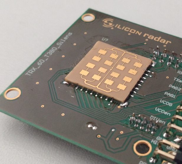
4.5 Antenna on Chip
Antennas can be placed directly on Silicon IC. This allows very fine structures down to a few microns size, however, the total antenna area is limited. High performance integrated antenna structures are possible up to THz-range.
Advantages:
- Antennas are directly connected to IC structures allowing maximum efficiency
- Suitable for 60 GHz to THz designs
- Suitable for high bandwidths
- Not very expensive in series production
Disadvantages:
- Antenna area is limited, therefore narrow antenna beams are not possible
- Maybe more expensive for prototyping
- Not suitable for low frequencies such as 24 GHz
5 Lenses & Reflectors
5.1 Lenses
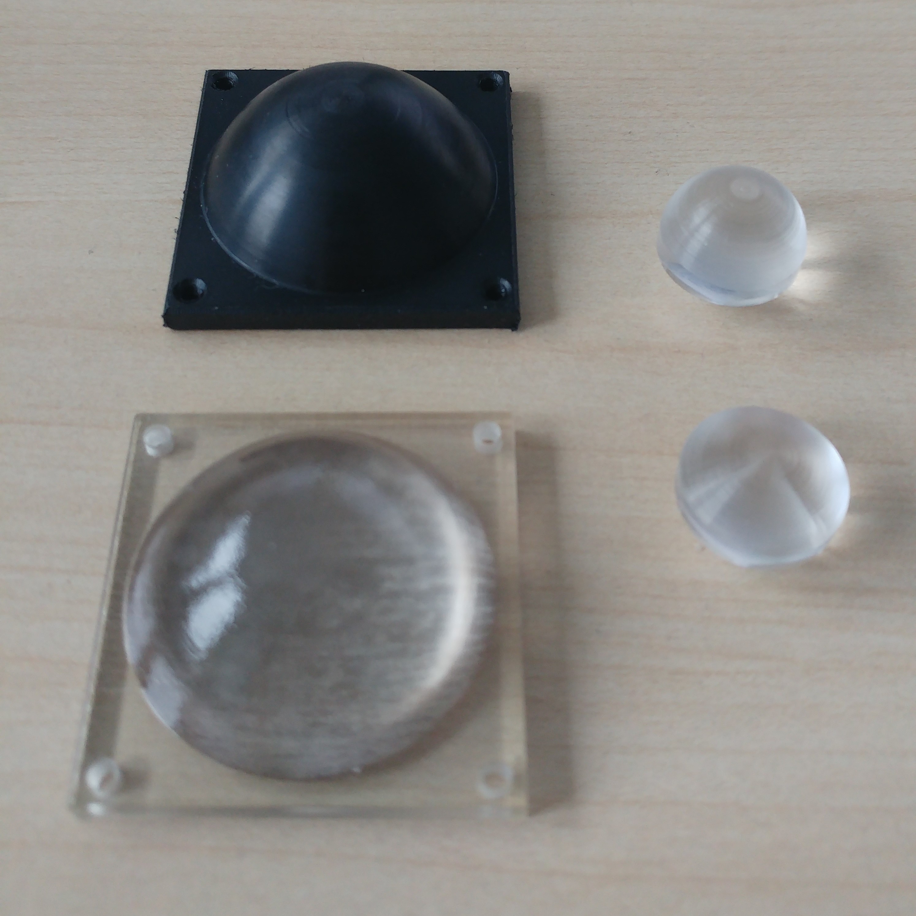
Any lens that works for other electromagnetic waves can work for radar, for example, LED lenses. Typically, lenses are made from a plastic or acrylic material and come in different sizes and forms. The size and form is important to
- focus the beam - achieve a collecting or diffusing effect,
- increase the gain of the signal (usually around 10 dB, maybe more),
- adapt the coupling into the air or other media.
Our evaluation kits and some lenses already have holes to mount them. Other lenses might have to be glued to the front end or mounted in another way. If you need lenses, please contact our sales team. We also provide the lens data on request. Some lenses are shown in Figure 1. The standard black lens on the left for our evaluation kits is made from HDPE. The small lens on the right is a lathed acrylic lens.
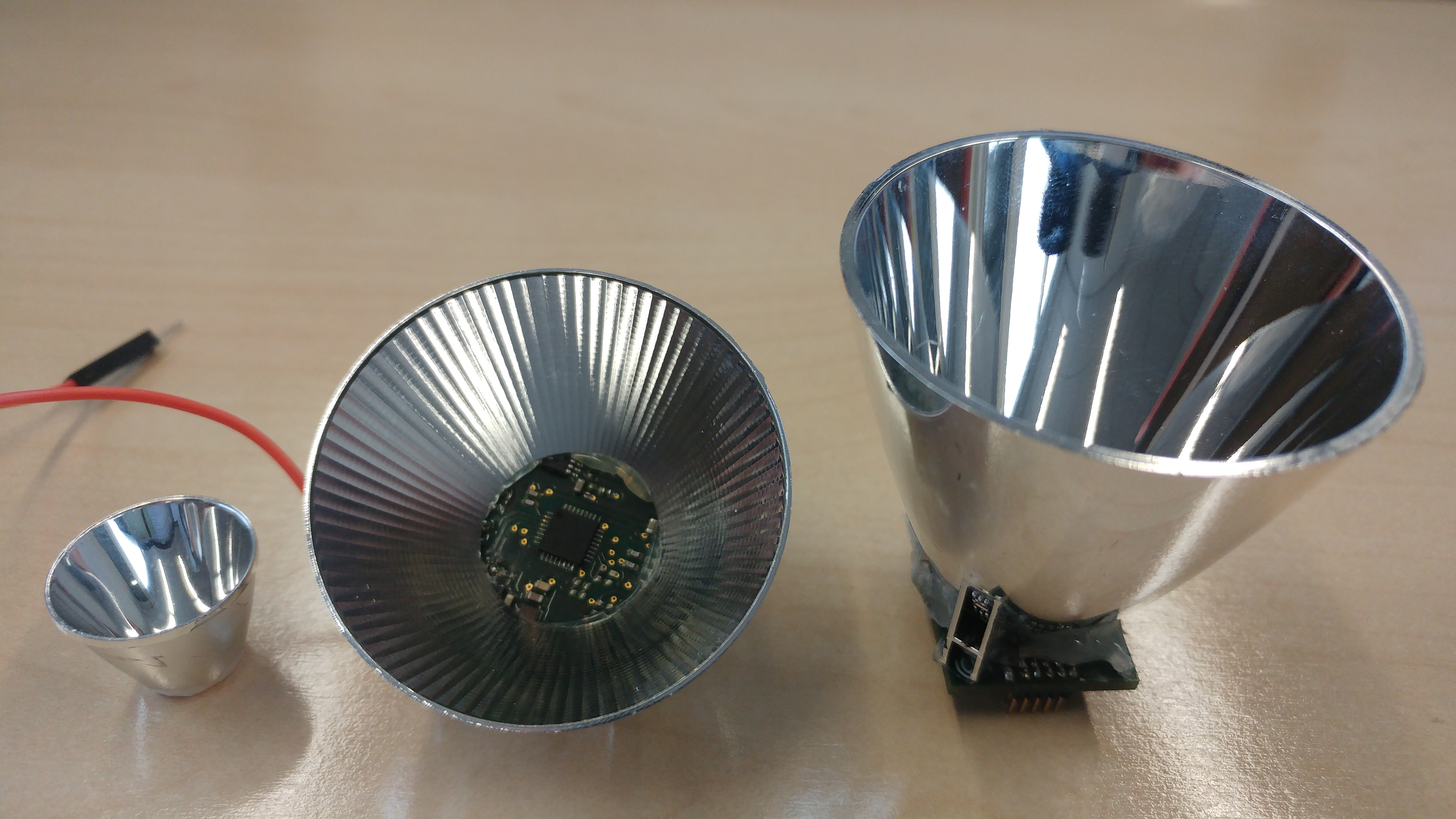
5.2 Reflectors
LED reflectors are very suited to be used for our radars. These reflectors can increase the gain of the signal more than lenses because any side lobes are redirected to the main viewing direction of the radar. We tested, for example, the following ranges (for big targets like buildings) in some quick experiments
- 140 m with a reflector on the SiRad Simple (120 GHz),
- 200 m with a reflector on the SiRad Easy.
Typically, LED reflectors are made from a plastic material covered with metal and are available in different sizes. Bigger reflectors usually lead to higher gain. Reflectors mostly need to be glued to the radar (hot glue works just fine). However, care must be taken not to shortcut any signals on the radar with the metal cover of the reflector. We found the reflectors by TE Connectivity to be very suitable, for example, TE Connectivity 1-2154430-1, available from Mouser.