Radar
Contents
1 What is Radar
Radars are systems that detect targets or objects and their ranges or velocities, but can also track targets, identify or classify targets, or image targets. The applications are numerous and include industrial, civil, and military systems. Radars are also mounted on robots, vehicles, and airplanes. The name Radar itself is an old acronym for RAdio Detecting And Ranging.
1.1 History of Radar
- 1904: Christian Hülsmeyer, patent "Process for reporting distant metallic objects to an observer by means of electric waves"
- 1940s: Würzburg giant from Telefunken f = 560 MHz, B = 500 kHz, m = 11 t, range: 60-80 km Search and track aircraft
- 1942: Frequency hopping method, Hedy Lamarr + George Antheil: using Piano rolls to rapidly change RF frequencies to remotely control torpedoes.
Problem: Synchronizing transmitter and receiver. Solution: synchronously running piano rolls (punch tape). Although no known working device was ever produced, the technology today is the basis for RF standards like Bluetooth and 3G as well as military Radars and communication Radars.
- 1951: Synthetic Aperture Radar: Enlarging antenna aperture using the controlled motion of the system. The method yields high-resolution images of objects and landscapes
- 1970‘s: Georadar and first automotive Radar
- 1995: first series car with ACC (Mitsubishi)
1.2 Concept
A Radar transmits electromagnetic waves and receives electromagnetic waves that have been reflected on objects in a region of interest. Most surfaces reflect incoming waves at least partly back towards the source. The reflected waves contain information about the object. This can information includes its range, velocity, angular direction, size, and shape. Most Radar systems contain at least a transmitter and receiver, an antenna, and a processor. Today, those parts can all be integrated with a very small silicon chip, which enables Radar systems that also fit a lot of new and future use cases.
2 Common Acronyms
- ADC
- Analog to Digital Converter - a unit that transforms analog signals to digital signals.
- ASIC
- Application Specific Integrated Circuit - an IC designed for a specific application.
- Automotive Band
- Frequency band specified for automotive applications, 24 GHz, 77 GHz - 79 GHz.
- BGA
- Ball Grid Array - a packaging technology for silicon chips where the contacts of the chips are connected to metal balls (dots of solder) arranged in an array under the molded chip, also see #LGA, #PGA.
- Bistatic Radar
- Radar system with separate antennas for the receive and transmit channel.
- BIST-Circuit
- Build In Self-Test-Circuit - a structure in an IC or circuit that simplifies testing or enables a self-test of the circuit.
- Bonding / Wire Bonding
- A method to connect a silicon chip to peripherals by attaching wires from the chip to the peripherals.
- Bump Chip
- Alternative method to wire bonding to connect a silicon chip to peripherals.
- DSP
- Digital Signal Processing - methods to process a signal in the digital domain, such as filtering or analysis, e.g. Fast Fourier Transformation, also see #FFT.
- ESD
- Electrostatic Discharge - an electricity flow between two electrically charged objects that can cause damage to electronic devices.
- ESD-Structures
- Structures in a circuit / IC, which protect the circuit from destruction by ESD. In Silicon Radar's ICs commonly made up of special diodes.
- FAM
- Film Assisted Moulding - a method to mold silicon ICs in a package. It allows free spaces in the molding.
- FFT
- Fast Fourier Transformation - a method to convert analog signals from the time domain to the frequency domain to be able to analyse their frequencies and signal strengths, also see #DSP.
- Flip Chip
- Alternative method to wire bonding to connect a silicon chip to peripherals. The chip is mounted "top side down".
- FMCW
- Frequency Modulated Continuous Wave - a method to operate a radar system.
- FMEA
- Failure Mode and Effects Analysis - a method to calculate the time to live and risks of failure.
- Foundry
- Factory or company that produces silicon chips. Usually, technologies and chip designs are not interchangeable between foundries, since they use different technologies and processes.
- FSK
- Frequency Shift Keying - a method to encode a digital signal using analog frequencies above and below a carrier frequency.
- Globtop
- Moulding on a silicon chip without a mold. The chip is attached to a carrier and the molding mass is "dropped" on the chip.
- GWR
- Guided Wave Radar - a method where a radar impulse is sent along a guiding tube or probe, mainly used for distance and level measurement in liquid or bulky media.
- ISM-Bands
- License free Industrial-Scientific-Medical bands for millimeter waves.
- Lead Frame
- Frame to which a silicon chip is attached, e.g. by wire bonding or flip-chip technology before it is molded.
- LGA
- Land Grid Array - a packaging technology for silicon chips where the contacts of the chips are connected to flat patches of metal arranged in an array under the molded chip, also see #BGA, #PGA.
- LNA
- Low Noise Amplifier.
- MIMO System
- Multiple Input Multiple Output System - a system using more than one recipient and transmit antenna, also see #MISO System.
- MISO System
- Multiple Input Single Output System - a system using more than one receive antennas and only one transmit antenna, also see #MIMO System.
- MMIC
- Millimeter Wave IC - an IC designed to generate or process millimeter waves.
- Monostatic Radar
- A radar system using only a single common antenna for the transmit and receive channel.
- MPW
- Multi Project Wafer - a technology of a foundry where several silicon chips for the various projects are produced on the same wafer.
- MTBF
- Mean Time Between Failures - the average time before a device fails again after a failure/repair, also see #MTTF.
- MTTF
- Mean Time To Failure - the average time before a device fails (this is not the live time), also see #MTBF.
- Multistatic Radar
- A radar system using separate antennas for the receive and transmit channel.
- Passive Radar
- A radar system without a transmitting channel. It processes signals and their reflections transmitted by mobile devices, radio stations, and so on.
- PGA
- Pin Grid Array - a packaging technology for silicon chips where the contacts of the chips are connected to pins of metal arranged in an array under the molded chip, also see #BGA, #LGA.
- Phase noise
- The difference between the real phase and a theoretical phase of a signal seen in the time domain.
- PLL
- Phase Locked Loop - a method to stabilize or adjust a frequency in a circuit by looping the output signal back to the input and comparing the phase of both signals.
- PRI
- Pulse Repetition Interval - the time between two pulses, also see #PRF.
- PRF
- Pulse repetition Frequency - Frequency of repeating pulses, also see #PRI.
- Pulse Radar
- A radar system using short pulses as a transmit signal.
- Pulse Compression
- A method to compress a complex signal to a short pulse.
- SPI
- Serial Peripheral Interface - a digital communication interface.
- TPV
- Through Polymer Via - a molding technology where conducting vias are created from a silicon chip to the surface of the molding mass.
- VCO
- Voltage Controlled Oscillator - an oscillator where the output frequency can be controlled by an input voltage.
3 Radar Principles
3.1 General Information
Being the interface circuits that process radio frequencies for Radars, depending on applications, there are different types of Radar front ends that can be selected to be most suitable for the requirements. Radar front ends may be categorized by the operating frequencies, the way they interface with antennas, and the way they process the information. Some generic Radar front ends are described here.
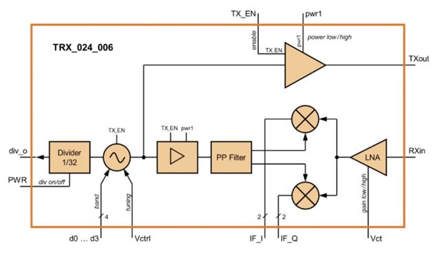
3.2 Continuous-Wave (CW) Radar Front Ends
CW Radar is a basic radar structure that uses a continuous frequency source for radio wave transmission. Therefore, it relies on the Doppler effect in the detection of an object. Since the signal from the frequency source has to be continuously transmitted, the CW Radar has an advantage in terms of the effective transmitted power compared to pulsed Radars. The frequency of the source can be unmodulated or modulated. If not modulated, only the velocity of a moving object can be detected based on the Doppler frequency shift. If the frequency of the signal source is modulated (called FMCW: Frequency-Modulated Continuous-Wave) by means of varying the tuning voltage of an oscillator, the distance of an object can also be measured. In general, the modulation signal on the tuning voltage of an oscillator can be saw-tooth or triangular waves. This can be done conveniently by interfacing a Radar front end (via frequency divider output) with an off-chip phase-locked loop (PLL) that can generate the modulation signal. At Silicon Radar, the 24-GHz Radar front end TRX_024_006 and 007 can be operated both in CW and FMCW modes.
3.3 Phased-Array Radar Front Ends
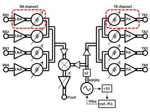
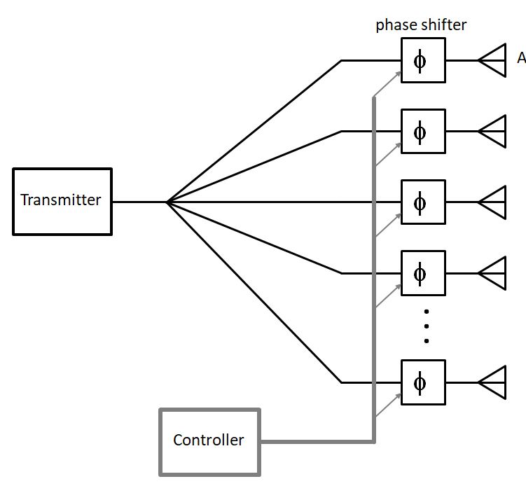
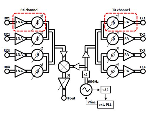
Phased-array radar is based on the beam-forming concept that the phases of the electrical signals that are sent to the antennas in an array are appropriately adjusted in such a way that, when combined spatially, it increases the intensity of the signal in the desired direction. This process can be done by using phase shifters as shown in the diagram in Figure 2. In this diagram of a 120-GHz Radar, the phase shifters can be found together with the low-noise amplifier (LNA) in the receiver and with the power amplifier (PA) in the transmitter.
3.4 MIMO Radar Front Ends
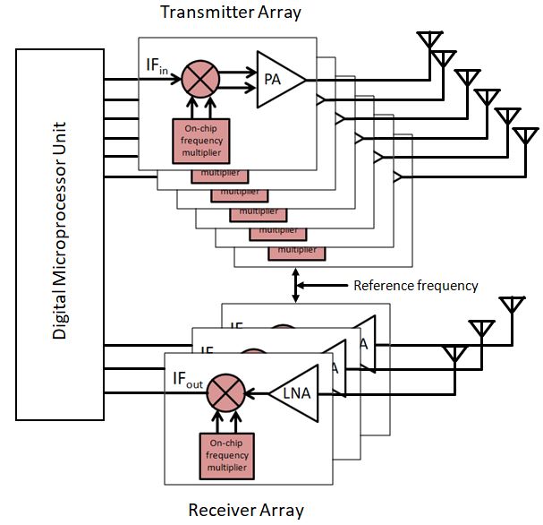
MIMO (Multiple-Input Multiple-Output) Radar front ends are similar to the phased-array Radars in the sense that they are both multiple-antenna systems. MIMO Radars utilize special digital signal processing techniques on multiple units of Radars to generate a virtual antenna array. Basically, a bigger virtual array representing more receive and transmit units can be created from a smaller number of actual receive and transmit units. Therefore, by processing the mutual signals between multiple units, a more powerful Radar system resulting from an array of transmitters and receivers can be realized without physically using the corresponding number of receivers and transmitters. A basic diagram of a MIMO Radar front end is shown in Figure 3.
3.5 Pulsed Radar Front Ends
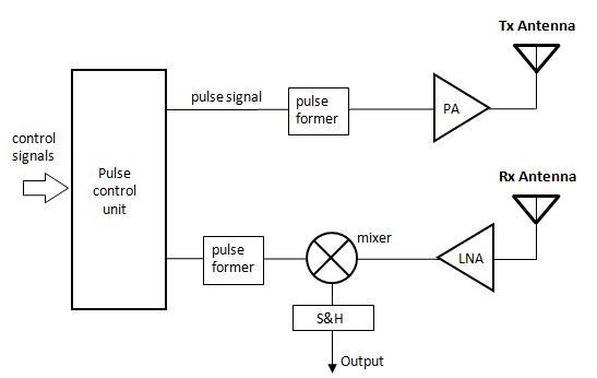
Pulsed Radar is a time-domain Radar system, in which a high-power and short electrical pulse are transmitted and the reflected pulse from an object is detected. By processing the time between the transmitted pulse and the reflected pulse, the distance of that object can be measured. The system may start the measurement of the time at the beginning of the transmitted pulse and finish counting the time after detecting the reflected signal. As shown in the basic diagram of Figure 4, the pulse control unit generates a square-wave pulse where the pulse former is used to re-shape to pulse to be suitable for transmission. In the receiver part, the same pulse shape is required as a template to down-convert the received pulse to be suitable for the sample and hold (S&H) circuit.
4 CW / FMCW / FSK
4.1 CW (Continuous Wave Radar)
CW radars which are the simplest form of radars operate continuously on a stable high frequency. It can be used to detect un stationary targets as distance measurement cannot be performed. Velocity information is extracted by the Doppler effect caused by motion between the target and the radar.
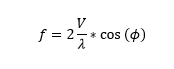
f = doppler frequency
λ = wavelength
V = target velocity
4.1.1 CW Radar Application
Please visit Speed Measurement section.
4.2 FMCW ((Frequency-Modulated Continuous Wave Radar)
FMCW radar generates linearly modulated pulses over time and commonly used frequency modulations are sawtooth and triangular, this can be done conveniently by interfacing a Radar front end (via frequency divider output) with an off-chip phase-locked loop (PLL) that can generate the modulation signal. Determining the range information of a target can be done due to the known frequency difference between received and transmit signals and time offset in contrast to CW radars. The frequency shift is determined by mixing the received signal from the target with the transmitted signal.
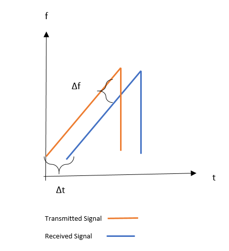
Figure one demonstrates the sawtooth modulated FMCW radar principle, from there time offset and frequency shift between received (blue) and transmitted (orange) signal can be obtained. Using FMCW radar, the target distance can be determined with high accuracy. Target distance is linear to the frequency shift (delta f in the graph above)and a greater difference in frequency refers to a high range. The frequency shift information is extracted by performing Fourier transform on digitalized data and the target range can be determined from the spectrum.
f= (B* 2R)/(T*c)
f=beat frequency B=Bandwidth
Range of the target affected by great numbers of factors such as antenna gain, Radar cross-section (RCS), Wavelength, atmospheric effects, etc.
4.2.1 FMCW Radar Application
Please visit Applications section.
4.3 FSK (Frequency Shift Keying)
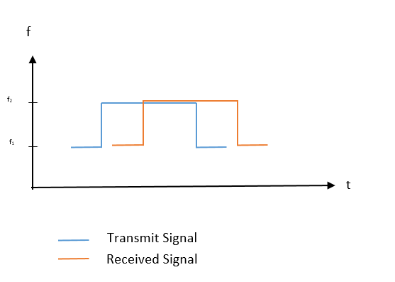
FSK is another radar technology and unlike CW and FMCW radars, transmitting frequency is switched between at least two frequencies. Since the frequency changes are less than the bandwidth of FMCW radars, the Doppler shift effect of the reflected target is the same but the phase is changed correlated with changes in the target range. Range and velocity measuring is applicable for FSK radars. f1 and f2 in the below pictures correspond to carrier frequencies of the radar sensor. Velocity information of the target is obtained from Doppler frequency however range is determined by comparing the phase of before and after frequency switched signals voltages.
5 MIMO
MIMO (Multiple Input Multiple Output) radars extend the traditional configuration of a single transmitter and receiver with the introduction of additional antennas. The motivation for introducing the multiple antennas is the ability to resolve the angular location of targets as well as making a system more robust to channel fading or other unfavorable operating conditions.
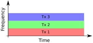
MIMO radar differs from Phased Array Radar, which similarly utilizes multiple receive and transmitting antennas, in that a MIMO signal transmits orthogonal waveforms from each individual transmit antennas, giving channel diversity across each of the individual transmitters to receiver path ("virtual channel").
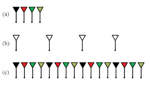
To achieve orthogonality, the transmitters must emit waveforms that are orthogonal in time, frequency, or code, as illustrated below.

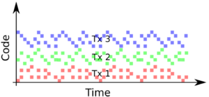
The collection of resulting virtual channels between each transmitter and receiver form the virtual array whose dimensions are determined by the spacing of antennas in both transmitter and receiver arrays.
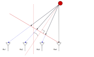
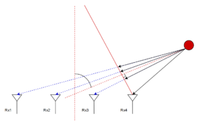
The result of constructing this virtual array gives rise to the ability to resolve angular information from the received signals by estimating the phase differences between receive antennas. The images below illustrate how objects at particular angles from an antenna array give rise to phase differences experienced by the individual antennas.
6 Phased Array
The Phased-array system stems from an idea to build antennas that can operate with signals in various directions without turning the antenna mechanically. Thus the cost, the weight, and the dimension of these types of systems can be reduced significantly. In this system, the phase of the antennas in an antenna array will be steered electronically to the required direction, hence the so-called phased-array antenna. By using this controlled manner, an electrical signal is sent to each antenna in an array with an appropriate phase in such a way that, when combined spatially, it increases the intensity of the signal in the desired direction, while minimizing the signals in other direction of the transmission. The main component to adjust the phase of the signal of each antenna element is called the phase shifter. The operation of the phase shifter is normally controlled by microcontrollers or microprocessors. A basic diagram of the phased-array antenna system is shown in Figure 1.
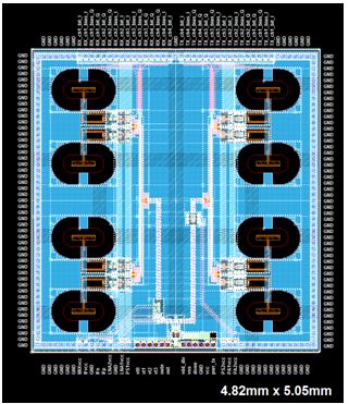
At Silicon Radar, phased-array radar has been developed at a millimeter-wave frequency, i.e., 120 GHz. For radar applications, the system consists of an array of receive, an array of transmitter a signal generator, and an intermediate-frequency (IF) section. The block diagram and the layout of a Silicon Radar 120-GHz phased-array chip are shown in Figure 2 and Figure 3, respectively. It can be noted that phase shifters are required on both transmitter and receiver arrays in order to selectively transmit and receive the signal in the required direction.
7 Six-Port Radar
7.1 General Information
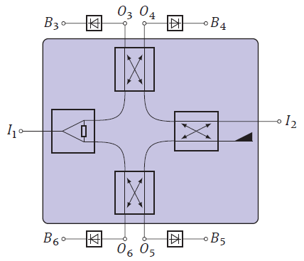
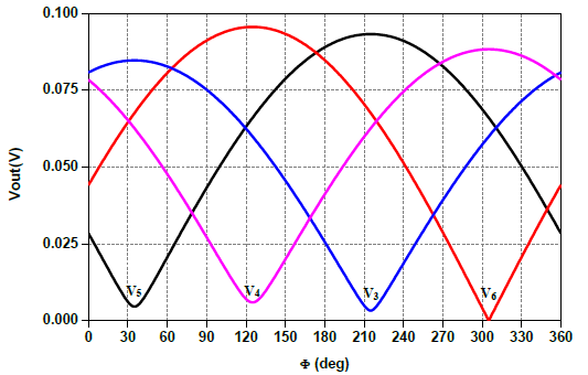
The Six-Port radar is a kind of radar that utilizes a specific principle (the so-called additive mixing property) of the Six-Port network. The Six-Port network was at the beginning developed to be used in a homodyne receiver. However, the principle can be applied to radar applications as well. The Six-Port network is a passive network consisting of six terminals, which are two input ports and four output ports. At the inputs, the two input signals are superimposed with each other under four different relative phase shifts. Depending on the phase difference and the amplitudes of the two input signals, constructive and destructive interaction takes place at the four output ports. A basic diagram of the Six-Port network is shown in Figure 1 [1]. Detailed mathematical analyses can also be found in [1]. A power divider is used to split the input power I1 to the two couplers, where the other inputs of them come from the other coupler that is interfaced with the input I2. The four DC voltages B3 to B6 are extracted from the four outputs O3 to O6 using envelope detectors. When plotted, the DC voltages B3 to B6 become quadrature functions of the phase difference between I1 and I2, as shown in Figure 2.
7.2 Six-Port Network in Radar
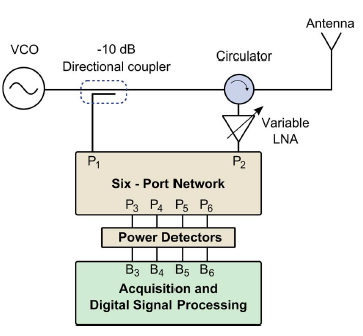
For radar applications, the Six-Port network is normally utilized in monostatic radar configuration, as shown in Figure 3. A voltage-controlled oscillator (VCO) is usually used as I1, while the antenna used at the same time for transmitting and receiving signal is used as I2 (via a coupler or circulator). It is important for the operation of the Six-Port network, that the power levels of I1 and I2 are similar. Therefore a variable-gain amplifier is normally used to amplify the power level of I2 to be similar to that of I1 which is from the VCO. It can be noted in the Six-Port radar that the frequency from the VCO does not need to be swept, as in the case of the FMCW radar.