Difference between revisions of "First Steps"
(→SiRad Simple® Evaluation Kit) |
|||
| (69 intermediate revisions by 4 users not shown) | |||
| Line 1: | Line 1: | ||
__NUMBEREDHEADINGS__ | __NUMBEREDHEADINGS__ | ||
| + | <div style="overflow-x: auto"> | ||
| + | {|style="text-align:center; width: 100%" | ||
| + | |style="background-color:#f2f2f2"|[[Evaluation #MIMO_Kit|SiRad MIMO]] | ||
| + | |style="background-color:#f2f2f2"|[[Evaluation #Evalkits_r4|SiRad Easy® r4]] | ||
| + | |style="background-color:#f2f2f2"|[[Evaluation #Evalkits|SiRad Easy®]] | ||
| + | |style="background-color:#f2f2f2"|[[Evaluation #Evalkits|SiRad Simple®]] | ||
| + | |style="background-color:#f2f2f2"|[[Evaluation #Eval_Boards|Eval Boards]] | ||
| + | |- | ||
| + | |[[File:Mimo_website_24_ghz.PNG|frameless|150px|link={{filepath:{{PAGENAME:Media:Mimo_website_24_ghz.PNG}}}}]] | ||
| + | |[[File:Evaluation-Evalkits-Easy r4-TRA 120 002.PNG|frameless|150px|link={{filepath:{{PAGENAME:Media:Evaluation-Evalkits-Easy r4-TRA 120 002.PNG}}}}]] | ||
| + | |[[File:Easy_with_lens.jpg|frameless|150px|link={{filepath:{{PAGENAME:Media:Easy_with_lens.jpg}}}}]] | ||
| + | |[[File:Simple.jpg|frameless|150px|link={{filepath:{{PAGENAME:Media:Simple.jpg}}}}]] | ||
| + | |[[File:EvalBoard_TRX_024_006_007.PNG|frameless|150px|link={{filepath:{{PAGENAME:Media:EvalBoard_TRX_024_006_007.PNG}}}}]] | ||
| + | |} | ||
| + | </div> | ||
| + | <!-- | ||
| + | <div style="overflow-x: auto"> | ||
| + | {| style="text-align:center; width:100%" | ||
| + | |+'''Table 1: Available SR-Evaluation Kits''' | ||
| + | |- | ||
| + | |style="width: 17%; min-width:130px; background-color:#f2f2f2"|<span style="color: black">'''EvalKit'''</span> | ||
| + | |style="width: 17%; background-color:#f2f2f2"|[[Evaluation #MIMO_Kit|SiRad MIMO]] | ||
| + | |style="width: 17%; background-color:#f2f2f2"|[[Evaluation #Evalkits_r4|SiRad Easy® r4]] | ||
| + | |style="width: 17%; background-color:#f2f2f2"|[[Evaluation #Evalkits|SiRad Easy®]] | ||
| + | |style="width: 17%; background-color:#f2f2f2"|[[Evaluation #Evalkits|SiRad Simple®]] | ||
| + | |style="width: 17%; background-color:#f2f2f2"|[[Evaluation #Eval_Boards|Eval Boards]] | ||
| + | |- | ||
| + | |style="background-color:#f2f2f2"|<span style="color: black">'''Integration of MMIC on PCB'''</span> | ||
| + | |style="text-align: left; padding-left: 1%; padding-right: 1%; vertical-align: top" | Plug-On MIMO Evaluation Board | ||
| + | |style="text-align: left; padding-left: 1%; padding-right: 1%; vertical-align: top" | Plug-On Evaluation Board | ||
| + | |style="text-align: left; padding-left: 1%; padding-right: 1%; vertical-align: top" | Plug-On Evaluation Board | ||
| + | |style="text-align: left; padding-left: 1%; padding-right: 1%; vertical-align: top" | All-in-One Evaluation Board | ||
| + | |style="text-align: left; padding-left: 1%; padding-right: 1%; vertical-align: top" | Stand-Alone Evaluation Board | ||
| + | |- | ||
| + | |style="background-color:#f2f2f2"|<span style="color: black">'''PCB-Stack'''</span> | ||
| + | |style="background-color:#f2f2f2; text-align: left; padding-left: 1%; padding-right: 1%; vertical-align: top" | | ||
| + | *Radar Front End[*1] | ||
| + | *Baseband Board</br> | ||
| + | *FPGA Carrier Board</br> | ||
| + | *MPSoC Module | ||
| + | |style="background-color:#f2f2f2; text-align: left; padding-left: 1%; padding-right: 1%; vertical-align: top" | | ||
| + | *Radar Front End[*1] | ||
| + | *Baseband Board</br> | ||
| + | *Breakout Board | ||
| + | |style="background-color:#f2f2f2; text-align: left; padding-left: 1%; padding-right: 1%; vertical-align: top" | | ||
| + | *Radar Front End[*1] | ||
| + | *Baseband Board</br> | ||
| + | *Processing Board | ||
| + | |style="background-color:#f2f2f2; text-align: left; padding-left: 1%; padding-right: 1%; vertical-align: top" | one layer – EvalBoard only | ||
| + | |style="background-color:#f2f2f2; text-align: left; padding-left: 1%; padding-right: 1%; vertical-align: top" | one layer – EvalBoard only | ||
| + | |- | ||
| + | |style="background-color:#f2f2f2"|<span style="color: black">'''Target Application'''</span> | ||
| + | |style="text-align: left; padding-left: 1%; padding-right: 1%; vertical-align: top" | Flexible and modular test set-up for investigation of use cases | ||
| + | |style="text-align: left; padding-left: 1%; padding-right: 1%; vertical-align: top" | Flexible and modular test set-up for investigation of use cases | ||
| + | |style="text-align: left; padding-left: 1%; padding-right: 1%; vertical-align: top" | Flexible and modular test set-up for investigation of use cases | ||
| + | |style="text-align: left; padding-left: 1%; padding-right: 1%; vertical-align: top" | Compact Test Set-up for investigation of the use case | ||
| + | |style="text-align: left; padding-left: 1%; padding-right: 1%; vertical-align: top" | Lab Test of MMIC parameters such as gain, linearity, … | ||
| − | [[File: | + | |- |
| + | |style="background-color:#f2f2f2"|<span style="color: black">'''Available for following MMICs'''</span> | ||
| + | |style="background-color:#f2f2f2; text-align: left; padding-left: 1%; padding-right: 1%; vertical-align: top" | Multi-Channel [ 2x4 ] | ||
| + | |style="background-color:#f2f2f2; text-align: left; padding-left: 1%; padding-right: 1%; vertical-align: top" | Single Channel | ||
| + | |style="background-color:#f2f2f2; text-align: left; padding-left: 1%; padding-right: 1%; vertical-align: top" | Single Channel | ||
| + | |style="background-color:#f2f2f2; text-align: left; padding-left: 1%; padding-right: 1%; vertical-align: top" | TRX_120_001 fixed | ||
| + | |style="background-color:#f2f2f2; text-align: left; padding-left: 1%; padding-right: 1%; vertical-align: top" | All 24 GHz MMICs[*2] | ||
| + | |- | ||
| + | |style="background-color:#f2f2f2"|<span style="color: black">'''Set-Up Example'''</span> | ||
| + | |[[File:Mimo_website_24_ghz.PNG|frameless|150px|link={{filepath:{{PAGENAME:Media:Mimo_website_24_ghz.PNG}}}}]] | ||
| + | |[[File:Evaluation-Evalkits-Easy r4-TRA 120 002.PNG|frameless|150px|link={{filepath:{{PAGENAME:Media:Evaluation-Evalkits-Easy r4-TRA 120 002.PNG}}}}]] | ||
| + | |[[File:Easy_with_lens.jpg|frameless|150px|link={{filepath:{{PAGENAME:Media:Easy_with_lens.jpg}}}}]] | ||
| + | |[[File:Simple.jpg|frameless|150px|link={{filepath:{{PAGENAME:Media:Simple.jpg}}}}]] | ||
| + | |[[File:EvalBoard_TRX_024_006_007.PNG|frameless|150px|link={{filepath:{{PAGENAME:Media:EvalBoard_TRX_024_006_007.PNG}}}}]] | ||
| + | |- | ||
| + | |} | ||
| + | </div> | ||
| − | + | [*1] exchangeable, each MMICs requires a different Front End</br> | |
| + | [*2] lead times may apply, please inquire for details | ||
| + | --> | ||
| + | This page contains a quick start guide for our evaluation kits. More detailed information can be found in the user guides available in the [https://siliconradar.com/wp/ download area]. | ||
| − | = SiRad Easy® = | + | = SiRad Easy® r4 Evalution Kit = |
| + | *Product information [https://siliconradar.com/datasheets/Product_Information_EvalKits_R4.html] | ||
| − | + | *Product Sheet [https://siliconradar.com/datasheets/Product_Sheet_SiRad_Easy_r4_RFE_TRX_120_001.html], [https://siliconradar.com/datasheets/Product_Sheet_SiRad_Easy_r4_RFE_TRA_120_002.html], [https://siliconradar.com/datasheets/Product_Sheet_SiRad_Easy_r4_RFE_TRX_024_046.html] and [https://siliconradar.com/datasheets/Product_Sheet_SiRad_Easy_r4_Base_Board.html] | |
| + | |||
| + | *WebGUI Guide [https://siliconradar.com/datasheets/User_Guide_WebGUI_Easy_Simple.html] | ||
| + | |||
| + | *Ecosystem [https://siliconradar.com/datasheets/Overview_Easy_r4_Modules.html] | ||
| + | |||
| + | *Schematics [https://login.siliconradar.com/] | ||
| + | |||
| + | *Accessories List [https://siliconradar.com/datasheets/Product_Sheet_SiRad_Easy_r4_Boards_Accessories.html] | ||
| + | |||
| + | *Collimator Lens [https://siliconradar.com/datasheets/Datasheet_Collimator_Lens.html] | ||
| + | |||
| + | *TRA_120_002 SiRad front end datasheet [https://siliconradar.com/datasheets/Datasheet_TRA_120_002.html] | ||
| + | |||
| + | *TRX_120_001 SiRad front end datasheet [https://siliconradar.com/datasheets/Datasheet_TRX_120_001.html] | ||
| + | |||
| + | *TRX_024_046 SiRad front end datasheet [https://siliconradar.com/datasheets/Datasheet_TRX_024_046.html] | ||
| + | |||
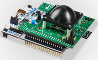
| + | = SiRad Easy® Evalution Kit = | ||
| + | After receiving SiRad Easy® Evalution Kit, as a first step please visit [https://login.siliconradar.com/ Customer Download Area] (you have to register at our site) and flash the kit according to your front end board. SiRad Easy® Evalution Kit has separate firmware for each front end and it is important to flash the correct firmware. Please see below links for hardware configuration / front end board setup: | ||
| + | *[[SiRad Easy 60 GHz Front End Board]] | ||
| + | |||
| + | *[[SiRad Easy 120 GHz Wideband Front End Board]] | ||
| + | |||
| + | *[[SiRad Easy 300 GHz Front End Board]] | ||
| + | |||
| + | *User Guide [https://siliconradar.com/datasheets/User_Guide_Easy.html] | ||
| + | |||
| + | *Protocol Description [https://siliconradar.com/datasheets/Protocol_Description_Easy.html] | ||
| + | |||
| + | *WebGUI Guide [https://siliconradar.com/datasheets/User_Guide_WebGUI_Easy_Simple.html] | ||
| + | |||
| + | *Schematics [https://login.siliconradar.com/] | ||
| + | |||
| + | *Collimator Lens [https://siliconradar.com/datasheets/Datasheet_Collimator_Lens.html] | ||
| + | |||
| + | *TRX_120_001 SiRad front end datasheet [https://siliconradar.com/datasheets/Datasheet_TRX_120_001.html] | ||
| − | * | + | *TRA_120_002 SiRad front end datasheet [https://siliconradar.com/datasheets/Datasheet_TRA_120_002.html] |
| − | |||
| − | |||
| − | |||
| − | |||
| − | |||
| − | + | *TRA_024_007 SiRad front end datasheet [https://siliconradar.com/datasheets/Datasheet_TRX_024_007.html] | |
| − | + | *TRA_024_006 SiRad front end datasheet [https://siliconradar.com/datasheets/Datasheet_TRX_024_006.html] | |
| − | + | *RF Low Noise Amplifier LNA_024_004 datasheet [https://siliconradar.com/datasheets/Datasheet_LNA_024_004.html] | |
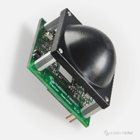
| − | = | + | = SiRad Simple® Evaluation Kit = |
| − | + | *User Guide [https://siliconradar.com/datasheets/User_Guide_Simple.html] | |
| − | + | *Protocol description [https://siliconradar.com/datasheets/Protocol_Description_Simple.html] | |
| − | |||
| − | |||
| − | |||
| − | + | *WebGUI Guide [https://siliconradar.com/datasheets/User_Guide_WebGUI_Easy_Simple.html] | |
| − | + | *Schematics [https://login.siliconradar.com/] | |
| + | *Collimator Lens [https://siliconradar.com/datasheets/Datasheet_Collimator_Lens.html] | ||
| − | + | *TRX_120_001 SiRad front end datasheet [https://siliconradar.com/datasheets/Datasheet_TRX_120_001.html] | |
| − | + | = SiRad MIMO Evaluation Kit= | |
Requirements: | Requirements: | ||
| − | *MS Windows | + | *MS Windows 10 |
| − | * | + | *ST-LINK USB driver (STSW-LINK009)[http://www.st.com/content/st_com/en/products/embedded-software/development-tool-software/stsw-link009.html] |
| − | + | *Software Package by Silicon Radar [https://login.siliconradar.com] | |
| − | + | *5V Barrel Jack Power Supply (5.5mm) | |
| − | *Software Package by Silicon Radar | + | *Ethernet Connection & Cable |
| − | * | + | |
| + | <b>Starting the Kit:</b> | ||
| + | |||
| + | The Evaluation Kit interfaces with the PC through an Ethernet connection, so firstly connect the kit to the PC using an Ethernet cable. | ||
| − | + | Connecting the 5V power supply starts the kit. Once successfully powered, LED D2 located near the SD card should blink green for a few seconds indicating that Linux is successfully booting from the SD card. | |
| − | + | <b>DHCP Connection to PC:</b> | |
| − | + | The connection to the PC is managed by a DHCP protocol, and can be run as either a client or server. | |
| − | + | In most cases, where the Kit is connected directly to the Ethernet port of a PC which has it's IP address set automatically, the Kit will be used as a server. | |
| − | + | == DHCP Connection to PC - Possibility One - Kit as Client == | |
| − | + | On startup, the kit will search for a DHCP server to become a client of. Once the kit is subscribed to the DHCP server, any client running the GUI will be able to connect to it and run the Kit. | |
| − | |||
| − | |||
| − | |||
| − | + | == DHCP Connection to PC - Possibility One - Kit as Server == | |
| − | + | If there is no DHCP server present, the kit will time out searching for the server after approximately 60 seconds and become a DHCP server itself. Once this happens any client connected to the kit (i.e. a user PC) will be assigned an IP address by the kit and will be able to connect to and run the kit via the GUI. | |
Latest revision as of 08:20, 14 July 2021

This page contains a quick start guide for our evaluation kits. More detailed information can be found in the user guides available in the download area.
Contents
1 SiRad Easy® r4 Evalution Kit
- Product information [1]
- WebGUI Guide [6]
- Ecosystem [7]
- Schematics [8]
- Accessories List [9]
- Collimator Lens [10]
- TRA_120_002 SiRad front end datasheet [11]
- TRX_120_001 SiRad front end datasheet [12]
- TRX_024_046 SiRad front end datasheet [13]
2 SiRad Easy® Evalution Kit
After receiving SiRad Easy® Evalution Kit, as a first step please visit Customer Download Area (you have to register at our site) and flash the kit according to your front end board. SiRad Easy® Evalution Kit has separate firmware for each front end and it is important to flash the correct firmware. Please see below links for hardware configuration / front end board setup:
- User Guide [14]
- Protocol Description [15]
- WebGUI Guide [16]
- Schematics [17]
- Collimator Lens [18]
- TRX_120_001 SiRad front end datasheet [19]
- TRA_120_002 SiRad front end datasheet [20]
- TRA_024_007 SiRad front end datasheet [21]
- TRA_024_006 SiRad front end datasheet [22]
- RF Low Noise Amplifier LNA_024_004 datasheet [23]
3 SiRad Simple® Evaluation Kit
- User Guide [24]
- Protocol description [25]
- WebGUI Guide [26]
- Schematics [27]
- Collimator Lens [28]
- TRX_120_001 SiRad front end datasheet [29]
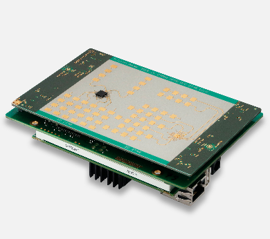
4 SiRad MIMO Evaluation Kit
Requirements:
- MS Windows 10
- ST-LINK USB driver (STSW-LINK009)[30]
- Software Package by Silicon Radar [31]
- 5V Barrel Jack Power Supply (5.5mm)
- Ethernet Connection & Cable
Starting the Kit:
The Evaluation Kit interfaces with the PC through an Ethernet connection, so firstly connect the kit to the PC using an Ethernet cable.
Connecting the 5V power supply starts the kit. Once successfully powered, LED D2 located near the SD card should blink green for a few seconds indicating that Linux is successfully booting from the SD card.
DHCP Connection to PC:
The connection to the PC is managed by a DHCP protocol, and can be run as either a client or server.
In most cases, where the Kit is connected directly to the Ethernet port of a PC which has it's IP address set automatically, the Kit will be used as a server.
4.1 DHCP Connection to PC - Possibility One - Kit as Client
On startup, the kit will search for a DHCP server to become a client of. Once the kit is subscribed to the DHCP server, any client running the GUI will be able to connect to it and run the Kit.
4.2 DHCP Connection to PC - Possibility One - Kit as Server
If there is no DHCP server present, the kit will time out searching for the server after approximately 60 seconds and become a DHCP server itself. Once this happens any client connected to the kit (i.e. a user PC) will be assigned an IP address by the kit and will be able to connect to and run the kit via the GUI.