Difference between revisions of "24 GHz Transceivers"
| (28 intermediate revisions by 4 users not shown) | |||
| Line 1: | Line 1: | ||
__NUMBEREDHEADINGS__ | __NUMBEREDHEADINGS__ | ||
| − | + | <div style="overflow-x: auto"> | |
| − | {| style="text-align:center; width: | + | {| style="text-align:center; width:100%" |
| − | |style="background-color:#f2f2f2"|<span style="color: black">'''Front End'''</span> | + | |style="width: 14%; background-color:#f2f2f2"|<span style="color: black">'''Front End'''</span> |
| − | |style="background-color:#f2f2f2"|<span style="color: black">'''Status of IC'''</span> | + | |style="width: 14%; background-color:#f2f2f2"|<span style="color: black">'''Status of IC'''</span> |
| − | |style="background-color:#f2f2f2"|<span style="color: black">'''Package'''</span> | + | |style="width: 15%; background-color:#f2f2f2"|<span style="color: black">'''Package'''</span> |
| − | |style="background-color:#f2f2f2"|<span style="color: black">'''Antenna Solutions'''</span> | + | |style="width: 15%; min-width:130px; background-color:#f2f2f2"|<span style="color: black">'''Antenna Solutions'''</span> |
| − | |style="background-color:#f2f2f2"|<span style="color: black">'''Evaluation / Sensor'''</span> | + | |style="width: 14%; min-width:130px; background-color:#f2f2f2"|<span style="color: black">'''Evaluation / Sensor'''</span> |
| + | |style="width: 28%; min-width:250px; background-color:#f2f2f2"|<span style="color: black">'''Typical Applications'''</span> | ||
|- | |- | ||
|style="text-align: left; padding-left: 1%; padding-right: 1%; vertical-align: top"| | |style="text-align: left; padding-left: 1%; padding-right: 1%; vertical-align: top"| | ||
Single Channel Transceiver / Receiver | Single Channel Transceiver / Receiver | ||
| − | *[https://siliconradar.com/datasheets/ | + | *[https://siliconradar.com/datasheets/Datasheet_TRX_024_006.html TRX_024_006] |
| − | *[https://siliconradar.com/datasheets/ | + | *[https://siliconradar.com/datasheets/Datasheet_TRX_024_007.html TRX_024_007] |
|style="text-align: left; padding-left: 1%; padding-right: 1%; vertical-align: top"| | |style="text-align: left; padding-left: 1%; padding-right: 1%; vertical-align: top"| | ||
*Series production | *Series production | ||
| Line 17: | Line 18: | ||
*[[(FAM) QFN|QFN]] | *[[(FAM) QFN|QFN]] | ||
|style="text-align: left; padding-left: 1%; padding-right: 1%; vertical-align: top"| | |style="text-align: left; padding-left: 1%; padding-right: 1%; vertical-align: top"| | ||
| − | * | + | *[[Antennas#Antenna on PCB|Antenna on PCB]] |
| − | * | + | *[[Antennas#Eternal Antenna|External Antenna]] |
|style="text-align: left; padding-left: 1%; padding-right: 1%; vertical-align: top"| | |style="text-align: left; padding-left: 1%; padding-right: 1%; vertical-align: top"| | ||
[https://siliconradar.com/wiki/Evalkits SiRad Easy®]</br> | [https://siliconradar.com/wiki/Evalkits SiRad Easy®]</br> | ||
[[Eval Boards]] | [[Eval Boards]] | ||
| + | |style="text-align: left; padding-left: 1%; padding-right: 1%; vertical-align: top"| | ||
| + | [[Distance, Level, Position|Range Finding]], [[Distance, Level, Position|Level Probing]],</br> | ||
| + | [[Distance, Level, Position|Position Finding]], [[Distance, Level, Position|Presence Detection]],</br> | ||
| + | [[Motion, Speed, Vibration|Flow Rate Measurement]], [[Motion, Speed, Vibration|Motion Detection]],</br> | ||
| + | [[Motion, Speed, Vibration|Speed Measurement]], [[Material Analysis|Non-destructive Testing]],</br> | ||
| + | [[Material Analysis|Positioning]], [[Material Analysis|Surface Profiling]],</br> | ||
| + | [[Material Analysis|Thickness Measurement]] | ||
|- | |- | ||
|style="text-align: left; padding-left: 1%; padding-right: 1%; vertical-align: top; background-color:#f2f2f2"| | |style="text-align: left; padding-left: 1%; padding-right: 1%; vertical-align: top; background-color:#f2f2f2"| | ||
| Line 32: | Line 40: | ||
*[[(FAM) QFN|QFN]] | *[[(FAM) QFN|QFN]] | ||
|style="text-align: left; padding-left: 1%; padding-right: 1%; vertical-align: top; background-color:#f2f2f2"| | |style="text-align: left; padding-left: 1%; padding-right: 1%; vertical-align: top; background-color:#f2f2f2"| | ||
| − | * | + | *[[Antennas#Antenna on PCB|Antenna on PCB]] |
| − | * | + | *[[Antennas#Eternal Antenna|External Antenna]] |
|style="text-align: left; padding-left: 1%; padding-right: 1%; vertical-align: top; background-color:#f2f2f2"| | |style="text-align: left; padding-left: 1%; padding-right: 1%; vertical-align: top; background-color:#f2f2f2"| | ||
[https://siliconradar.com/wiki/Evalkits SiRad MIMO 24 GHz]</br> | [https://siliconradar.com/wiki/Evalkits SiRad MIMO 24 GHz]</br> | ||
[[Eval Boards]] | [[Eval Boards]] | ||
| + | |style="text-align: left; padding-left: 1%; padding-right: 1%; vertical-align: top; background-color:#f2f2f2"| | ||
| + | [[Distance, Level, Position|Level Probing]], [[Motion, Speed, Vibration|Flow Rate Measurement]],</br> | ||
| + | [[Motion, Speed, Vibration|Motion Detection]], [[Motion, Speed, Vibration|Speed Measurement]],</br> | ||
| + | [[Objects, Presence, Shape|Shape Detection]], [[Material Analysis|Surface Profiling]] | ||
|} | |} | ||
| + | </div> | ||
(1) Qualified after JEDEC; MSL</br> | (1) Qualified after JEDEC; MSL</br> | ||
| Line 43: | Line 56: | ||
__FORCETOC__ | __FORCETOC__ | ||
| − | + | = TRX_024_006 = | |
| − | = | + | {| |
| + | [[File:TRX_06_frei.png|border|right|220px|link={{filepath:{{PAGENAME:Media:TRX_06_frei.png}}}}]] | ||
| + | |} | ||
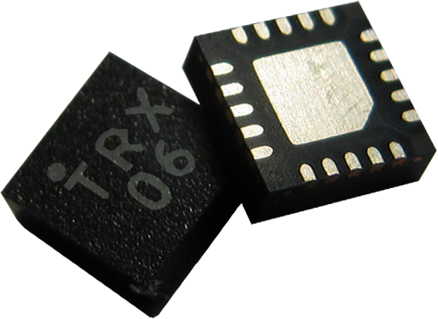
The IC is an integrated transceiver circuit for the 24-GHz ISM band in the frequency range 24.0 GHz – 24.25 GHz. It includes a low-noise amplifier (LNA) with gain control, quadrature mixers, a poly-phase filter, a voltage controlled oscillator with band switching, and a divide-by-32 circuit. The receiver can be powered down if PWR_RX pin is supplied with 0 V. The gain of the receiver can be digitally controlled by Vct pin: Vct = 3.3 V sets the receiver in high gain mode, Vct = 0 V sets the receiver in low gain mode. The output power of the transmitter can be controlled by the pwr1 input. The IC is fabricated in SiGe BiCMOS technology[https://www.ihp-microelectronics.com/en/services/mpw-prototyping/sigec-bicmos-technologies.html] using the bipolar part and the CMOS part. | The IC is an integrated transceiver circuit for the 24-GHz ISM band in the frequency range 24.0 GHz – 24.25 GHz. It includes a low-noise amplifier (LNA) with gain control, quadrature mixers, a poly-phase filter, a voltage controlled oscillator with band switching, and a divide-by-32 circuit. The receiver can be powered down if PWR_RX pin is supplied with 0 V. The gain of the receiver can be digitally controlled by Vct pin: Vct = 3.3 V sets the receiver in high gain mode, Vct = 0 V sets the receiver in low gain mode. The output power of the transmitter can be controlled by the pwr1 input. The IC is fabricated in SiGe BiCMOS technology[https://www.ihp-microelectronics.com/en/services/mpw-prototyping/sigec-bicmos-technologies.html] using the bipolar part and the CMOS part. | ||
| − | + | The TRXˍ024ˍ006 can be used in wireless communication systems and radar systems for the ISM band from 24.0 GHz to 24.25 GHz and for UWB applications between 23 GHz and 26 GHz. | |
| + | |||
| + | For more information please see [https://siliconradar.com/datasheets/Datasheet_TRX_024_006.html TRX_024_006 datasheet]. | ||
| − | + | Besides the TRXˍ024ˍ006, an IC variant with a divider division ratio of 1:8 is available as TRX_024_007, please see section below. | |
= TRX_024_007 = | = TRX_024_007 = | ||
| − | The IC is an integrated transceiver circuit for the 24-GHz ISM band in the frequency range 24.0 GHz – 24.25 GHz. It includes a low-noise amplifier (LNA) with gain control, quadrature mixers, a poly-phase filter, a voltage controlled oscillator with band switching, and a divide-by-8 circuit. The receiver can be powered down if PWR_RX pin is supplied with 0 V. The gain of the receiver can be digitally controlled by Vct pin: Vct = 3.3 V sets the receiver in high gain mode, Vct = 0 V sets the receiver in low gain mode. The output power of the transmitter can be controlled by the pwr1 input. The IC | + | The IC is an integrated transceiver circuit for the 24-GHz ISM band in the frequency range 24.0 GHz – 24.25 GHz. It includes a low-noise amplifier (LNA) with gain control, quadrature mixers, a poly-phase filter, a voltage controlled oscillator with band switching, and a divide-by-8 circuit. The receiver can be powered down if PWR_RX pin is supplied with 0 V. The gain of the receiver can be digitally controlled by Vct pin: Vct = 3.3 V sets the receiver in high gain mode, Vct = 0 V sets the receiver in low gain mode. The output power of the transmitter can be controlled by the pwr1 input. The IC has been fabricated in SiGe BiCMOS[https://www.ihp-microelectronics.com/en/services/mpw-prototyping/sigec-bicmos-technologies.html] technology by using the bipolar part and the CMOS part. |
| + | |||
| + | The TRXˍ024ˍ007 can be used in radar systems and wireless communication systems for the ISM band from 24.0 GHz to 24.25 GHz and for UWB applications between 23 GHz and 26 GHz. | ||
| − | + | For more information please see [https://siliconradar.com/datasheets/Datasheet_TRX_024_007.html TRX_024_007 datasheet]. | |
| − | + | Beside the TRXˍ024ˍ007, an IC variant with a divider division ratio of 1:32 is available as TRXˍ024ˍ006. | |
= FAQ: TRX_024_00* = | = FAQ: TRX_024_00* = | ||
| − | + | Please see [[FAQs]] page for frequently asked questions. | |
| − | |||
| − | |||
| − | |||
| − | |||
| − | |||
| − | |||
| − | |||
| − | |||
| − | |||
| − | |||
| − | |||
| − | |||
| − | |||
| − | |||
| − | |||
| − | |||
| − | |||
| − | |||
| − | |||
| − | |||
| − | |||
| − | |||
| − | |||
| − | |||
| − | |||
| − | |||
| − | |||
| − | |||
| − | |||
| − | |||
| − | |||
| − | |||
| − | |||
| − | |||
| − | |||
| − | |||
| − | |||
| − | |||
| − | |||
| − | |||
| − | |||
| − | |||
| − | |||
| − | |||
| − | |||
| − | |||
| − | |||
| − | |||
| − | |||
| − | |||
Latest revision as of 10:10, 4 May 2021
| Front End | Status of IC | Package | Antenna Solutions | Evaluation / Sensor | Typical Applications |
|
Single Channel Transceiver / Receiver |
|
Range Finding, Level Probing, | |||
|
Multi Channel Transceiver
|
|
Level Probing, Flow Rate Measurement, |
(1) Qualified after JEDEC; MSL
Contents
1 TRX_024_006
The IC is an integrated transceiver circuit for the 24-GHz ISM band in the frequency range 24.0 GHz – 24.25 GHz. It includes a low-noise amplifier (LNA) with gain control, quadrature mixers, a poly-phase filter, a voltage controlled oscillator with band switching, and a divide-by-32 circuit. The receiver can be powered down if PWR_RX pin is supplied with 0 V. The gain of the receiver can be digitally controlled by Vct pin: Vct = 3.3 V sets the receiver in high gain mode, Vct = 0 V sets the receiver in low gain mode. The output power of the transmitter can be controlled by the pwr1 input. The IC is fabricated in SiGe BiCMOS technology[1] using the bipolar part and the CMOS part.
The TRXˍ024ˍ006 can be used in wireless communication systems and radar systems for the ISM band from 24.0 GHz to 24.25 GHz and for UWB applications between 23 GHz and 26 GHz.
For more information please see TRX_024_006 datasheet.
Besides the TRXˍ024ˍ006, an IC variant with a divider division ratio of 1:8 is available as TRX_024_007, please see section below.
2 TRX_024_007
The IC is an integrated transceiver circuit for the 24-GHz ISM band in the frequency range 24.0 GHz – 24.25 GHz. It includes a low-noise amplifier (LNA) with gain control, quadrature mixers, a poly-phase filter, a voltage controlled oscillator with band switching, and a divide-by-8 circuit. The receiver can be powered down if PWR_RX pin is supplied with 0 V. The gain of the receiver can be digitally controlled by Vct pin: Vct = 3.3 V sets the receiver in high gain mode, Vct = 0 V sets the receiver in low gain mode. The output power of the transmitter can be controlled by the pwr1 input. The IC has been fabricated in SiGe BiCMOS[2] technology by using the bipolar part and the CMOS part.
The TRXˍ024ˍ007 can be used in radar systems and wireless communication systems for the ISM band from 24.0 GHz to 24.25 GHz and for UWB applications between 23 GHz and 26 GHz.
For more information please see TRX_024_007 datasheet.
Beside the TRXˍ024ˍ007, an IC variant with a divider division ratio of 1:32 is available as TRXˍ024ˍ006.
3 FAQ: TRX_024_00*
Please see FAQs page for frequently asked questions.