SiRad Easy 300 GHz Front End Board
Contents
1 EvalKit Easy – Operation with Front End TRA_300_030 in wide-band modus
Since the EvalKit Easy is not recognizing radar front ends with wide band-operation capability a manual adaptation may become necessary.
2 Cable Connection
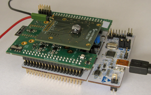
For the power supply to the front end a separate connection is required. The red power cable connects the 5V pin of the Front End board as shown in Fig. 1 with the pin E5V of the Easy board.
Fig. 1: EvalKit Easy with 300GHz Front End
3 Software Start
To launch the software evaluation platform please follow this routine:
- connect the WebGUI
- press the black reset button on the Easy Board (cf. Fig. 1)
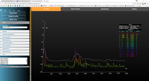
In the best case you already have some useful output if you are pointing the radar head towards a defined target, e.g. the ceiling. In the example shown in Fig. 2 this obstacle/object has a distance of around 2m, an additional peak next to the DC peak (left limit of the diagram) can be caused by the operator. This situation describes the measurement result as it should look like.
Fig. 2: Graph of a radar measurement with one obstacle in 2m distance as it should look like [click to enlarge].
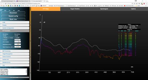
But maybe you may end up with a measurement graph rather similar to the one shown in Fig. 3.
Fig. 3: Resulting graph of a radar measurement, if operation conditions are not properly chosen [click to enlarge].
In such case the radar board operation and parameter setting needs to be reviewed as described in Section 4.
4 Parameter Setting
Whatever measurement graph you receive, please continue with the following steps:
- Go to RF Parameters tab (cf. Fig. 17 in the user guide)
 o	Leave the Selector Field "Front End" unchanged at 24, 60 or 122GHz, since it will not influence the further measurement.
 o	Set the VCO devider to 128
 o	Insert a Bandwidth (MHz) of 40'000 MHz as start value and increase later to the maximum bandwidth used
 o	Set the Base frequency (MHz) to 289'000 MHz.
- Go to BB Processing tab
 o	Adjust ADC clock divider to around 1-2ms or more (please watch the DC peaks)
 o	Adjust Number of samples to 1024 or more
 o	Adjust FFT size to 1024
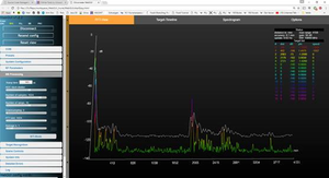
After you have performed all steps you should get an output similar to the one in Fig. 4.
Fig. 4: Radar Measurement following the parameter setting, still targeting an object in a distance of 2 meters [click to enlarge].
5 Return to Operation with automatic recognition of Radar Front Ends
For operation of SiRad Easy radar front ends with automatic recognition exchange the front end boards as previously used and restart operation.


