Difference between revisions of "Eval Boards"
| (11 intermediate revisions by 2 users not shown) | |||
| Line 1: | Line 1: | ||
__NUMBEREDHEADINGS__ | __NUMBEREDHEADINGS__ | ||
| + | <div style="overflow-x: auto"> | ||
| + | {|style="text-align:center; width: 100%" | ||
| + | |style="background-color:#f2f2f2"|[https://siliconradar.com/wiki/MIMO_Kit#SiRad_MIMO_r2 SiRad MIMO r2] | ||
| + | |style="background-color:#f2f2f2"|[https://siliconradar.com/wiki/MIMO_Kit#SiRad_MIMO_-_24_GHz SiRad MIMO] | ||
| + | |style="background-color:#f2f2f2"|[https://siliconradar.com/wiki/Evalkits_r4 SiRad Easy® r4] | ||
| + | |style="background-color:#f2f2f2"|[https://siliconradar.com/wiki/Evalkits SiRad Easy®] | ||
| + | |style="background-color:#f2f2f2"|[https://siliconradar.com/wiki/Evalkits SiRad Simple®] | ||
| + | |style="background-color:#f2f2f2"|[https://siliconradar.com/wiki/Eval_Boards Eval Boards] | ||
| + | |- | ||
| + | |[[File:24 GHz MIMO r2 Schraege.png|frameless|150px|link={{filepath:{{PAGENAME:Media:24 GHz MIMO r2 Schraege.png}}}}]] | ||
| + | |[[File:Mimo_website_24_ghz.PNG|frameless|150px|link={{filepath:{{PAGENAME:Media:Mimo_website_24_ghz.PNG}}}}]] | ||
| + | |[[File:Evaluation-Evalkits-Easy r4-TRA 120 002.PNG|frameless|150px|link={{filepath:{{PAGENAME:Media:Evaluation-Evalkits-Easy r4-TRA 120 002.PNG}}}}]] | ||
| + | |[[File:Easy_with_lens.jpg|frameless|150px|link={{filepath:{{PAGENAME:Media:Easy_with_lens.jpg}}}}]] | ||
| + | |[[File:Simple.jpg|frameless|150px|link={{filepath:{{PAGENAME:Media:Simple.jpg}}}}]] | ||
| + | |[[File:EvalBoard_TRX_024_006_007.PNG|frameless|150px|link={{filepath:{{PAGENAME:Media:EvalBoard_TRX_024_006_007.PNG}}}}]] | ||
| + | |} | ||
| + | </div> | ||
| − | For evaluation | + | For evaluation purposes, Silicon Radar offers Evaluation Boards (or just Eval Boards) suitable for the detailed characterization of our RF MMIC. Such investigations shall support the design-in for Sensor integration and usually are performed within the lab environment applying RF measurement instruments such as spectrum analyzers and vector analyzers. Please note that these Evaluation Boards are stand-alone boards that cannot be used in conjunction with our evaluation kits. For the latter different plug-on radar front end boards are needed. |
| − | The overview of available stand alone - Evaluation Boards is shown in the following Table 1. Please note that Evaluation Boards are | + | The overview of available stand-alone - Evaluation Boards is shown in the following Table 1. Please note that Evaluation Boards are manufactured on request. Therefore lead times will apply. |
| − | + | <div style="overflow-x: auto"> | |
| − | |+Table 1: Stand-Alone Evaluation Boards | + | {| style="text-align: center; width: 60%" |
| + | |+'''Table 1: Stand-Alone Evaluation Boards''' | ||
|- | |- | ||
| − | |Board name / for chip | + | |style="width: 15%; min-width:100px; background-color:#f2f2f2"|<span style="color: black">'''Board name / for chip'''</span> |
| − | |Frequency | + | |style="width: 12%; min-width:100px; background-color:#f2f2f2"|<span style="color: black">'''Frequency'''</span> |
| − | |Order Nr. | + | |style="width: 12%; min-width:100px; background-color:#f2f2f2"|<span style="color: black">'''Order Nr.'''</span> |
| − | |Variants | + | |style="width: 14%; min-width:100px; background-color:#f2f2f2"|<span style="color: black">'''Variants'''</span> |
| − | |Picture | + | |style="width: 15%; background-color:#f2f2f2"|<span style="color: black">'''Picture'''</span> |
|- | |- | ||
| − | |RX_024_004 | + | |style="text-align: left; padding-left: 1%; padding-right: 1%; vertical-align: top"|RX_024_004 |
| − | |24 GHz | + | |style="text-align: left; padding-left: 1%; padding-right: 1%; vertical-align: top"|24 GHz |
| − | |000009 | + | |style="text-align: left; padding-left: 1%; padding-right: 1%; vertical-align: top"|000009 |
| − | | | + | |style="text-align: left; padding-left: 1%; padding-right: 1%; vertical-align: top"| |
| − | |[[File:EvalBoard_RX_024_004.PNG| | + | |style="padding-left: 1%; padding-right: 1%; vertical-align: top"|[[File:EvalBoard_RX_024_004.PNG|frameless|150px|link={{filepath:{{PAGENAME:Media:EvalBoard_RX_024_004.PNG}}}}]] |
|- | |- | ||
| − | |RX2_024_006 | + | |style="text-align: left; padding-left: 1%; padding-right: 1%; vertical-align: top; background-color:#f2f2f2"|RX2_024_006 |
| − | |24 GHz | + | |style="text-align: left; padding-left: 1%; padding-right: 1%; vertical-align: top; background-color:#f2f2f2"|24 GHz |
| − | |000024 | + | |style="text-align: left; padding-left: 1%; padding-right: 1%; vertical-align: top; background-color:#f2f2f2"|000024 |
| − | | | + | |style="text-align: left; padding-left: 1%; padding-right: 1%; vertical-align: top; background-color:#f2f2f2"| |
| − | | | + | |style="padding-left: 1%; padding-right: 1%; vertical-align: top; background-color:#f2f2f2"| |
|- | |- | ||
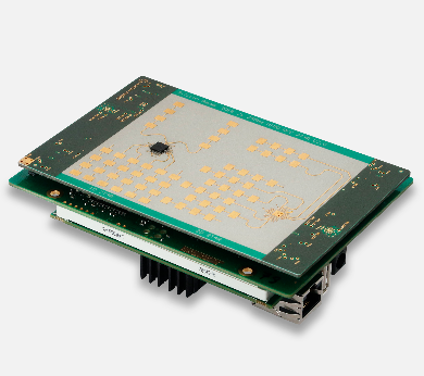
| − | |TRX_024_006 | + | |style="text-align: left; padding-left: 1%; padding-right: 1%; vertical-align: top"|TRX_024_006 |
| − | |24 GHz | + | |style="text-align: left; padding-left: 1%; padding-right: 1%; vertical-align: top"|24 GHz |
| − | |000007 | + | |style="text-align: left; padding-left: 1%; padding-right: 1%; vertical-align: top"|000007 |
| − | | | + | |style="text-align: left; padding-left: 1%; padding-right: 1%; vertical-align: top"| |
| − | |[[File:EvalBoard_TRX_024_006_007.PNG| | + | |style="padding-left: 1%; padding-right: 1%; vertical-align: top"|[[File:EvalBoard_TRX_024_006_007.PNG|frameless|150px|link={{filepath:{{PAGENAME:Media:EvalBoard_TRX_024_006_007.PNG}}}}]] |
|- | |- | ||
| − | |TRX_024_007 | + | |style="text-align: left; padding-left: 1%; padding-right: 1%; vertical-align: top; background-color:#f2f2f2"|TRX_024_007 |
| − | |24 GHz | + | |style="text-align: left; padding-left: 1%; padding-right: 1%; vertical-align: top; background-color:#f2f2f2"|24 GHz |
| − | |000008 | + | |style="text-align: left; padding-left: 1%; padding-right: 1%; vertical-align: top; background-color:#f2f2f2"|000008 |
| − | | | + | |style="text-align: left; padding-left: 1%; padding-right: 1%; vertical-align: top; background-color:#f2f2f2"| |
| − | |[[File:EvalBoard_TRX_024_006_007.PNG| | + | |style="padding-left: 1%; padding-right: 1%; vertical-align: top; background-color:#f2f2f2"|[[File:EvalBoard_TRX_024_006_007.PNG|frameless|150px|link={{filepath:{{PAGENAME:Media:EvalBoard_TRX_024_006_007.PNG}}}}]] |
|- | |- | ||
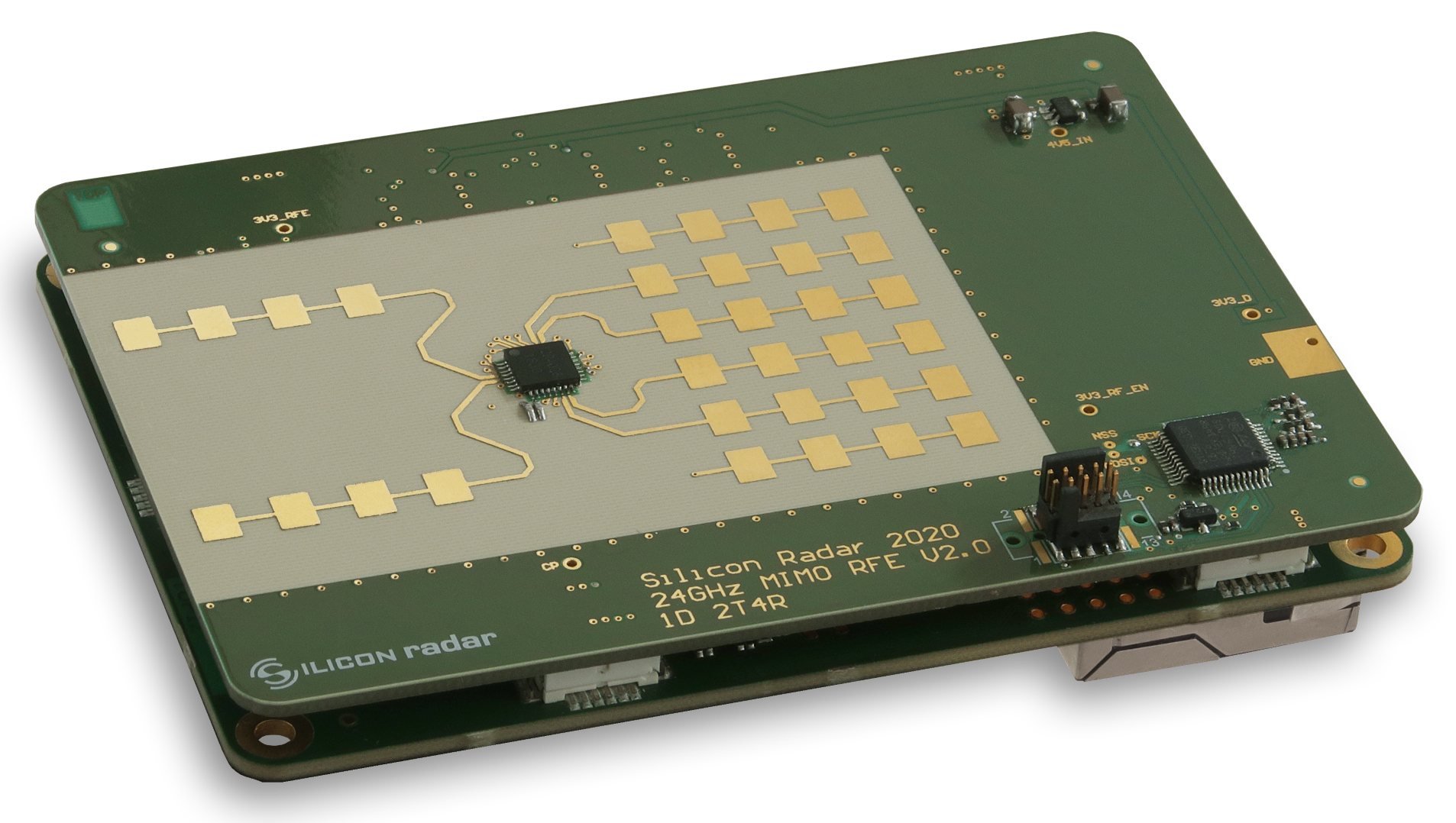
| − | |T2R4_024_010 | + | |style="text-align: left; padding-left: 1%; padding-right: 1%; vertical-align: top"|T2R4_024_010 |
| − | |24 GHz | + | |style="text-align: left; padding-left: 1%; padding-right: 1%; vertical-align: top"|24 GHz |
| − | |000280 | + | |style="text-align: left; padding-left: 1%; padding-right: 1%; vertical-align: top"|000280 |
| − | |different RF connectors [*] | + | |style="text-align: left; padding-left: 1%; padding-right: 1%; vertical-align: top"|different RF connectors [*] |
| − | |[[File:EvalBoard_T2R4_024_010.PNG| | + | |style="padding-left: 1%; padding-right: 1%; vertical-align: top"|[[File:EvalBoard_T2R4_024_010.PNG|frameless|150px|link={{filepath:{{PAGENAME:Media:EvalBoard_T2R4_024_010.PNG}}}}]] |
|- | |- | ||
| − | |LNA_024_004 | + | |style="text-align: left; padding-left: 1%; padding-right: 1%; vertical-align: top; background-color:#f2f2f2"|LNA_024_004 |
| − | |24 GHz | + | |style="text-align: left; padding-left: 1%; padding-right: 1%; vertical-align: top; background-color:#f2f2f2"|24 GHz |
| − | |000010 | + | |style="text-align: left; padding-left: 1%; padding-right: 1%; vertical-align: top; background-color:#f2f2f2"|000010 |
| − | | | + | |style="text-align: left; padding-left: 1%; padding-right: 1%; vertical-align: top; background-color:#f2f2f2"| |
| − | | | + | |style="padding-left: 1%; padding-right: 1%; vertical-align: top; background-color:#f2f2f2"| |
|} | |} | ||
| + | </div> | ||
| − | [*] depending on the required signal power there is a choice between RF connectors with standard frequency bandwidth and with high frequency bandwidth. | + | [*] depending on the required signal power there is a choice between RF connectors with standard frequency bandwidth and with high-frequency bandwidth. |
| − | In case there are further details needed or other evaluation solutions required please contact our Sales and Support Team for further assistance. | + | In case there are further details needed or other evaluation solutions required please contact our [https://siliconradar.com/contact-support-distributors/ Sales and Support Team] for further assistance. |
Latest revision as of 15:34, 26 January 2022

For evaluation purposes, Silicon Radar offers Evaluation Boards (or just Eval Boards) suitable for the detailed characterization of our RF MMIC. Such investigations shall support the design-in for Sensor integration and usually are performed within the lab environment applying RF measurement instruments such as spectrum analyzers and vector analyzers. Please note that these Evaluation Boards are stand-alone boards that cannot be used in conjunction with our evaluation kits. For the latter different plug-on radar front end boards are needed.
The overview of available stand-alone - Evaluation Boards is shown in the following Table 1. Please note that Evaluation Boards are manufactured on request. Therefore lead times will apply.
| Board name / for chip | Frequency | Order Nr. | Variants | Picture |
| RX_024_004 | 24 GHz | 000009 | 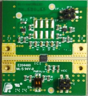
| |
| RX2_024_006 | 24 GHz | 000024 | ||
| TRX_024_006 | 24 GHz | 000007 | 
| |
| TRX_024_007 | 24 GHz | 000008 |
| |
| T2R4_024_010 | 24 GHz | 000280 | different RF connectors [*] | 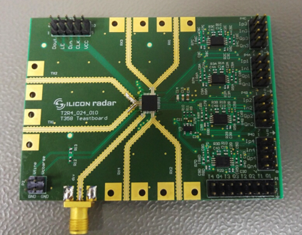
|
| LNA_024_004 | 24 GHz | 000010 |
[*] depending on the required signal power there is a choice between RF connectors with standard frequency bandwidth and with high-frequency bandwidth.
In case there are further details needed or other evaluation solutions required please contact our Sales and Support Team for further assistance.