Difference between revisions of "SiRad Simple"
| (37 intermediate revisions by 4 users not shown) | |||
| Line 1: | Line 1: | ||
| + | __NUMBEREDHEADINGS__ | ||
== Drivers == | == Drivers == | ||
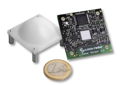
| − | + | [[File:EvalKit_SiRad_Simple_wiki.jpg|frameless|right|link={{filepath:{{PAGENAME:Media:EvalKit_SiRad_Simple_wiki.jpg}}}}]] | |
| − | + | '''1.1 Where can I get the driver to connect the SiRad Simple® ?''' | |
| − | + | :You need an FTDI cable (delivered with the sensor). You can download the latest FTDI driver (VCP driver) for your FTDI cable from the FTDI Chip Website [http://www.ftdichip.com/Drivers/VCP.htm]. | |
| − | + | '''1.2 I installed the FTDI driver for the SiRad Simple® but it does not show up.''' | |
| − | + | :Please open the Device Manager in Windows and unfold the ‘Ports (COM & LPT)’ section. You should see a couple of ports there. Now unplug and plug your SiRad Simple® sensor. The sensor is installed properly if you can see another port show up, usually named ‘USB Serial Port (COMx)’ or similar. If this is not the case, please check your connection and if the device has power. Remove the FTDI driver and start over with the FTDI driver installation. | |
| − | + | '''1.3 The FTDI driver for the SiRad Simple® does not work properly.''' | |
| − | + | :We recommend using a cable with FTDI chipset (delivered with the sensor) instead of cheaper alternatives since a lot of our customers found the cheaper alternatives to be very unstable. | |
| − | + | == Sensor Behavior & Range == | |
| − | + | '''3.1 How is the resolution defined?''' | |
| − | |||
| − | + | :We define the resolution as the ability to separate two targets in range. The resolution is only dependent on the selected bandwidth. With 1 GHz bandwidth the resolution is 15 cm, 6 GHz bandwidth equals 2.5 cm resolution. In practice, target recognition works from twice the resolution. | |
| − | + | '''3.2 How is the accuracy defined?''' | |
| − | |||
| − | |||
| − | |||
| − | |||
| − | |||
| − | |||
| − | |||
| − | |||
| − | |||
| − | + | :We define accuracy as the maximum error of the measured distance to a single target. It is dependent on the number of samples, the bandwidth, the downsampling and the FFT size. If the FFT size is twice the number of samples, the accuracy is two times less than the resolution. We can reach about 1 mm accuracy, also see Section 3.3.2 of the User Guide for the formula. | |
| − | + | '''3.3 Is there a minimum range / blind spot when using the SiRad Simple®?''' | |
| − | |||
| − | |||
| − | |||
| − | + | :The minimum range depends on the selected bandwidth. 1 GHz bandwidth works from about 30 cm, 6 GHz bandwidth works from about 7 cm. The blind spot is approximately as wide as once or twice the resolution. | |
| − | + | '''3.4 Can something be detected within the minimum range / blind spot?''' | |
| − | |||
| − | |||
| − | |||
| − | + | :Going below the bandwidth-dictated minimum range leads to an increased DC-offset in the FFT output. It could be used to detect ‘something is nearby’ but this is very application-specific. | |
| − | + | '''3.5 What is the maximum range of the SiRad Simple®?''' | |
| − | + | :The maximum range is dependent on the target. The SiRad Simple® Evaluation Kit reaches about 40 m with strong targets like buildings. | |
| − | + | '''3.6 Can the range of the sensor be increased?''' | |
| − | |||
| − | |||
| − | + | :You can increase the range by assembling the lens delivered with the SiRad Simple® Evaluation Kit, however, the opening angle will decrease. Larger detection distances are possible using bigger lenses or well-designed patch array antennas. | |
| − | + | '''3.7 How is the field of view of the SiRad Simple®?''' | |
| − | |||
| − | |||
| − | + | :The area covered by the radar over distance is dependent on the field of view of the sensor. Without a lens, the SiRad Simple® sensor has an opening angle of +/-30 degrees (-6dB). With the lens delivered with the sensor, this can be narrowed to about +/- 4 degrees. | |
| − | + | '''3.8 How can I get directional information from the SiRad Simple®?''' | |
| − | + | :SiRad Simple® has a single radar transceiver chip, which is not capable of giving directional information directly. It is possible, however, to use more than one SiRad Simple® sensor to get rudimentary directional information. | |
| − | + | == Protocol & RAW data == | |
| − | |||
| − | |||
| − | |||
| − | |||
| − | ''' | + | '''4.1 Can I use the the SiRad Easy® with own or third-party software?''' |
| − | + | :Yes. Please read the Protocol Description to get an idea how to control the SiRad Easy® with your own software or third-party software. Due to popular demand we have written some scripts for [[MATLAB & Octave]]. | |
| − | ''' | + | '''4.2 Can I activate raw data only or FFT data only output?''' |
| − | + | :Yes. Please read the Protocol Description about how to set up the SiRad Easy® for raw data only or FFT data only output. You may choose between unwindowed raw data and windowed raw data as well as complex FFT data and magnitude / phase data output. | |
| − | |||
| − | |||
| − | |||
| − | ''' | + | '''4.3 Can I use the sensor protocol with <any> device?''' |
| − | The | + | :Yes. The protocol can be used to talk to the SiRad Easy® from any device, it does not need to be a PC. |
| − | |||
| − | + | == Schematics & Firmware == | |
| − | |||
| − | |||
| − | |||
| − | |||
| − | |||
| − | |||
| − | |||
| − | |||
| − | |||
| − | |||
| − | |||
| − | |||
| − | |||
| − | |||
| − | |||
| − | |||
| − | |||
| − | |||
| − | |||
| − | |||
| − | |||
| − | |||
| − | |||
| − | |||
| − | |||
| − | |||
| − | = | ||
| − | |||
| − | |||
| − | |||
| − | |||
| − | |||
| − | |||
| − | |||
| − | |||
| − | |||
| − | |||
| − | |||
| − | |||
| − | |||
| − | |||
| − | |||
| − | |||
| − | |||
| − | |||
| − | |||
| − | |||
| − | |||
| − | |||
| − | |||
| − | |||
| − | |||
| − | |||
| − | |||
| − | |||
| − | |||
| − | |||
| − | |||
| − | |||
| − | |||
| − | |||
| − | |||
| − | ''' | + | '''5.1 Where can I find the schematics for the SiRad Simple®?''' |
| − | + | :You may apply for a non-disclosure agreement (NDA) with Silicon Radar to get the schematics. Please contact our [https://siliconradar.com/contact-support-distributors/ sales team]. | |
| − | |||
| − | |||
| − | ''' | + | '''5.2 Where can I get the source code for the SiRad Simple®?''' |
| − | SiRad Simple® | + | :The firmware on the SiRad Simple® sensor is not freely available but we are working on the SiRad library with a user friendly C programming API that we may provide to our customers. We do, however, provide the source code for the WebGUI and the Com2WebSocket tool. |
| − | |||
| − | |||
| − | == | + | == Lenses == |
| − | ''' | + | '''6.1 What happens, if you decrease or increase the distance between the board and the lens?''' |
| − | + | :You can manipulate the beam angle by this method - the closer you are mounting the lens the wider the angle. | |
| − | |||
| − | ''' | + | '''6.2 What is the lens made out of?''' |
| − | + | :The material is HDPE (high density poly ethylene). | |
| − | |||
| − | |||
| − | ''' | + | '''6.3 Where can I get your lens design?''' |
| − | + | :We can send you 3D data of the lens - a NDA has to be signed. Please contact our [https://siliconradar.com/contact-support-distributors/ sales team]. | |
| − | == | + | == Application notes == |
| − | ''' | + | '''7.1 Firmware Update''' |
| − | + | :Describes the [[Firmware Update|flash process]] for the SiRad Simple®. | |
| − | ''' | + | '''7.x Can you provide us with more application notes?''' |
| − | + | :We will expand this section in future with advice on specific applications. | |
| − | |||
| − | |||
Latest revision as of 15:25, 10 May 2021
Contents
1 Drivers
1.1 Where can I get the driver to connect the SiRad Simple® ?
- You need an FTDI cable (delivered with the sensor). You can download the latest FTDI driver (VCP driver) for your FTDI cable from the FTDI Chip Website [1].
1.2 I installed the FTDI driver for the SiRad Simple® but it does not show up.
- Please open the Device Manager in Windows and unfold the ‘Ports (COM & LPT)’ section. You should see a couple of ports there. Now unplug and plug your SiRad Simple® sensor. The sensor is installed properly if you can see another port show up, usually named ‘USB Serial Port (COMx)’ or similar. If this is not the case, please check your connection and if the device has power. Remove the FTDI driver and start over with the FTDI driver installation.
1.3 The FTDI driver for the SiRad Simple® does not work properly.
- We recommend using a cable with FTDI chipset (delivered with the sensor) instead of cheaper alternatives since a lot of our customers found the cheaper alternatives to be very unstable.
2 Sensor Behavior & Range
3.1 How is the resolution defined?
- We define the resolution as the ability to separate two targets in range. The resolution is only dependent on the selected bandwidth. With 1 GHz bandwidth the resolution is 15 cm, 6 GHz bandwidth equals 2.5 cm resolution. In practice, target recognition works from twice the resolution.
3.2 How is the accuracy defined?
- We define accuracy as the maximum error of the measured distance to a single target. It is dependent on the number of samples, the bandwidth, the downsampling and the FFT size. If the FFT size is twice the number of samples, the accuracy is two times less than the resolution. We can reach about 1 mm accuracy, also see Section 3.3.2 of the User Guide for the formula.
3.3 Is there a minimum range / blind spot when using the SiRad Simple®?
- The minimum range depends on the selected bandwidth. 1 GHz bandwidth works from about 30 cm, 6 GHz bandwidth works from about 7 cm. The blind spot is approximately as wide as once or twice the resolution.
3.4 Can something be detected within the minimum range / blind spot?
- Going below the bandwidth-dictated minimum range leads to an increased DC-offset in the FFT output. It could be used to detect ‘something is nearby’ but this is very application-specific.
3.5 What is the maximum range of the SiRad Simple®?
- The maximum range is dependent on the target. The SiRad Simple® Evaluation Kit reaches about 40 m with strong targets like buildings.
3.6 Can the range of the sensor be increased?
- You can increase the range by assembling the lens delivered with the SiRad Simple® Evaluation Kit, however, the opening angle will decrease. Larger detection distances are possible using bigger lenses or well-designed patch array antennas.
3.7 How is the field of view of the SiRad Simple®?
- The area covered by the radar over distance is dependent on the field of view of the sensor. Without a lens, the SiRad Simple® sensor has an opening angle of +/-30 degrees (-6dB). With the lens delivered with the sensor, this can be narrowed to about +/- 4 degrees.
3.8 How can I get directional information from the SiRad Simple®?
- SiRad Simple® has a single radar transceiver chip, which is not capable of giving directional information directly. It is possible, however, to use more than one SiRad Simple® sensor to get rudimentary directional information.
3 Protocol & RAW data
4.1 Can I use the the SiRad Easy® with own or third-party software?
- Yes. Please read the Protocol Description to get an idea how to control the SiRad Easy® with your own software or third-party software. Due to popular demand we have written some scripts for MATLAB & Octave.
4.2 Can I activate raw data only or FFT data only output?
- Yes. Please read the Protocol Description about how to set up the SiRad Easy® for raw data only or FFT data only output. You may choose between unwindowed raw data and windowed raw data as well as complex FFT data and magnitude / phase data output.
4.3 Can I use the sensor protocol with <any> device?
- Yes. The protocol can be used to talk to the SiRad Easy® from any device, it does not need to be a PC.
4 Schematics & Firmware
5.1 Where can I find the schematics for the SiRad Simple®?
- You may apply for a non-disclosure agreement (NDA) with Silicon Radar to get the schematics. Please contact our sales team.
5.2 Where can I get the source code for the SiRad Simple®?
- The firmware on the SiRad Simple® sensor is not freely available but we are working on the SiRad library with a user friendly C programming API that we may provide to our customers. We do, however, provide the source code for the WebGUI and the Com2WebSocket tool.
5 Lenses
6.1 What happens, if you decrease or increase the distance between the board and the lens?
- You can manipulate the beam angle by this method - the closer you are mounting the lens the wider the angle.
6.2 What is the lens made out of?
- The material is HDPE (high density poly ethylene).
6.3 Where can I get your lens design?
- We can send you 3D data of the lens - a NDA has to be signed. Please contact our sales team.
6 Application notes
7.1 Firmware Update
- Describes the flash process for the SiRad Simple®.
7.x Can you provide us with more application notes?
- We will expand this section in future with advice on specific applications.