What we do
Contents
1 Radar Front End Design
1.1 General Information
Since Radars use radio waves in the detection process, the Radar front ends are related to electronic circuits that operate with high-frequency signals. Depending on the purpose of applications, these frequencies range from hundreds of MHz up to hundreds of GHz, for example, defense systems of military radars and body scanners at airports. The design of Radar front ends involves the designs and developments of radio-frequency (RF) electronic circuit building blocks such as amplifiers, mixers, oscillators, and also some passive elements such as antennas.
1.2 Radar Front End Building Blocks
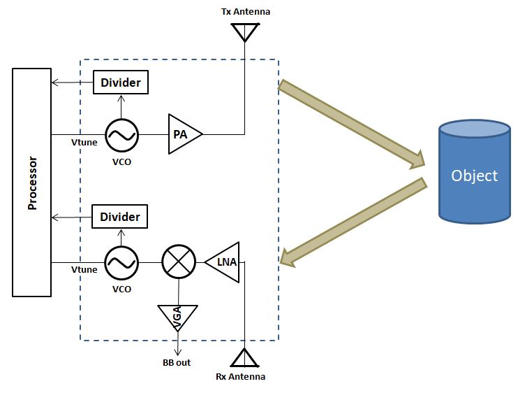
Radar front ends typically share a similar structure as shown in Figure 1. Some circuit building blocks used in Radar front ends are described here.
Amplifier: Amplifiers are used to amplify weak signals to a higher power. On the transmitter (Tx), it plays a role to enlarge the signal to a sufficient level to be transmitted through the antenna. This amplifier is referred to as a Power Amplifier (PA). On the receiver, since the signal reflected from an object and picked up by the antenna is at a very weak level, the amplifier on the receiver side has to amplify this signal by adding noise as little as possible to it. This amplifier is referred to as a Low-Noise Amplifier (LNA).
Mixer: Mixers are used for blending the signal at different frequencies and format together. On the transmitter side, a mixer is used to mix a sinusoidal and high-frequency signal from an oscillator to a modulation signal operating at a lower frequency and can be modulated. Then, this low-frequency signal is up-converted to a higher frequency and transmitted to the antenna. The mixer on the receiver side works in a reverse direction, i.e., to transform the high-frequency signal received at the antenna to a low-frequency signal for baseband processing.
Oscillator: Oscillators are used on the transmitter and the receiver. They are used to generate a reference signal that is stable in frequency, and if possible, in amplitude. The frequency can be tuned to cover the required bandwidth and shifts in temperature. Since the tuning is normally done by varying the control voltages, these oscillators are then referred to as Voltage-Controlled Oscillator (VCO).
Other blocks: Other circuits that can be found in Radar front ends may include a Variable-Gain Amplifier (VGA), which is used to amplify the low-frequency signal from the receive mixer before going out of the chip, a Frequency Divider, or sometimes just a Divider which is used for dividing the high-frequency signal from a VCO to a lower value in order to interface with an off-chip Phase-Locked Loop (PLL) for frequency stabilization and Baseband processors for interfacing between the Radar front end and a computational unit.
2 Generic Radar Front End Chips
2.1 Single-Channel Radar Transceiver
- Radar Functions: Range Finder; Presence Detection; Velocity; Basic Target Tracking
- Small IC dimensions; analog front-end; the concept of external PLL; ADC or µ-processor
- Wide selection of frequency bands
- At frequencies beyond 100GHz with OnChip-antennas
- Comparable simple sensor architecture
2.2 Multi-Channel-Transceiver for MIMO Radars
- Multiple transmit and receive channels integrated on one chip; comparable complex IC architecture;
- Radar Functions: Range Finder; Angular Information; Antenna Diversity; 2D/3D Visioning; Velocity; Advanced Target Tracking
- Significant IC dimensions, analog front-end; the concept of external PLL; ADC or µ-processor
- Only OffChip antennas because of chip dimension
2.3 Special Featured Chips – Ultra Wideband Radars
- Radar Functions: thickness measurement; spectroscopy, an excellent resolution with micrometer precision; life-signs detection; pressure sensors
- Small IC dimensions / Comparable simple sensor architecture
- OnChip antennas because of wideband characteristic
3 ASIC Design & Design Service
3.1 General Information
ASIC stands for Application-Specific Integrated Circuit, which means integrated circuits (IC) that are designed for specific purposes. These ICs are not commercially available in the markets. Therefore, the specification and the performance of the ASICs can be optimized to be most suitable for the applications and the requirements from customers. Normally, the number of chips obtained from ASIC designs are lower compared to those from the standard chips. ASICs offer several advantages compared to employing standard ICs, such as: - Customization and optimization to be most suitable for specific tasks - IP (intellectual property) in the design can be protected - Can be low cost and small lot number
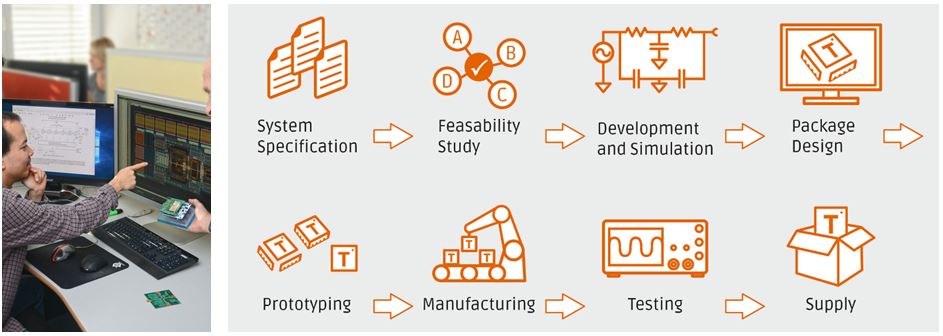
3.2 ASIC Design Process
The process of ASIC designs normally started with initial specifications from customers. With these basic requirements, a feasibility study will then be conducted, which can include fundamental verifications from simulations to check for realistic parameters. Then further discussions with customers based on the results of the feasibility study will be done to finalize the specifications. After these initial steps, the chip design process can start until the chip fabrication process has been done. The steps after this will include packaging (depending on the agreements), measurements, and documentation.
3.3 Design Service at Silicon Radar
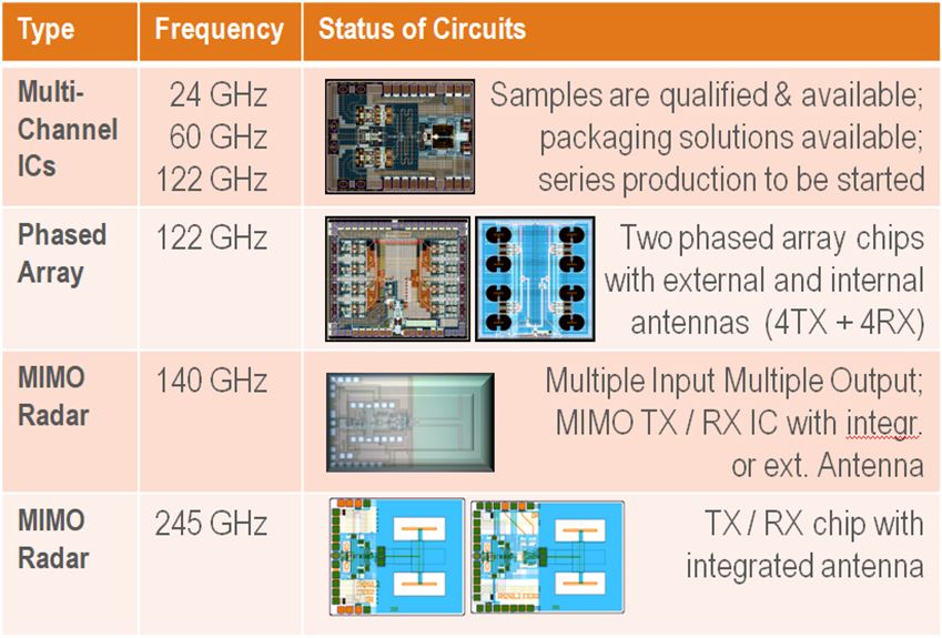
At Silicon Radar, ASIC design services of Radar chips are available in a wide frequency range starting from the low GHz region such as 10 GHz up to the sub-THz region such as 245 GHz. The types of Radars are also available in a wide variety such as single-channel FMCW Radar, multi-channel Radar, phased-array, and MIMO chips. The experience in Radar chip design at Silicon Radar is summarized (but not limited to) in Figure 2. The main technologies used in the designs are IHP SiGe BiCMOS such as 250-nm (for low-frequency circuits) and 130-nm processes (for high-frequency circuits).
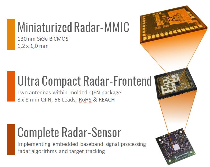
Not only ASIC Radar chip designs, but Silicon Radar also provides a full range of design flow starting from design consultant, chip design, antenna design, Radar module, and complete Radar sensor. The miniaturized Radar design service at Silicon Radar is summarized in Figure 3.
4 Sensor Design
4.1 General Information
Since Radars use radio waves in the detection process, the Radar front ends are related to electronic circuits that operate with high-frequency signals. Depending on the purpose of applications, these frequencies range from hundreds of MHz up to hundreds of GHz. The design of Radar sensors involves the development of PCBs and software around building blocks such as radar front ends, amplifiers, PLL & loop filters, ADC and microcontrollers, data interfaces, and passive elements.
4.2 Radar Sensor Building Blocks
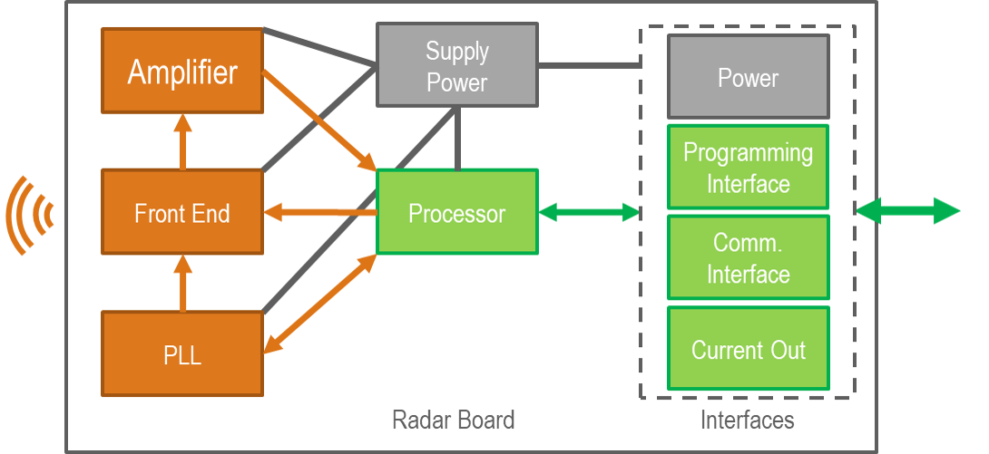
Radar sensors typically share a similar structure as shown in Figure 1. Some building blocks used in Radar sensors are described here.
Front End: The radar front end transmits and receives electromagnetic waves that reflect on objects. The reflected wave contains information about the object, for example, its speed or distance from the front end. Depending on the frequency of the electromagnetic waves, the antenna can be included with the front end, or connected externally. The front end is referred to as Radar Front End (RFE).
PLL & Loop Filter: The Phase-Looked-Loop and loop filter block controls the front end and sets its frequency into the operating range. The Phase-Looked-Loop also drives the ramp necessary to tune the front end over the chosen bandwidth. The loop filter is important for the correct operation of the front end and Phase-Looked-Loop. The Phase-Looked-Loop usually also compensates for any temperature or aging effects. The Phase-Looked-Loop and loop filter block are referred to as PLL.
Amplifier & Signal Filter: Amplifiers are used to amplify the signals coming from the radar front end. Since the signal reflected from an object and picked up by the radar front end is weaker than the signal that was initially sent out by the radar front end, the amplifier has to amplify this signal by adding as little noise as possible to the signal. This amplifier is referred to as the Base Band Amplifier (BBAmp). Further, some filtering is necessary on the signal. Filters are typically placed next to (before and after) the amplifier and referred to as Low-Pass (LP), High-Pass (HP), or Band-Pass (BP).
ADC & Microcontroller: The Analog-Digital-Converter (ADC) or microcontroller (uC) digitizes the radar signal for the following processing steps. Usually, the next processing steps include DC cancellation, windowing of the data, FFT calculation, and finally target extraction. The microcontroller also controls the different hardware parts such as RFE, PLL, and BBAmp.
Data Interfaces: Interfaces are needed to control the sensor via commands and to output data. Typical communication interfaces are GPIO pins, UART, SPI, Ethernet, and Wi-Fi.
5 How to Order/ Contact Us
Quotation
Please contact us, if you are interested in an offer regarding our products. We will send you a 'Request for Quotation' form (RfQ), since we need some information about your company and the intended use of our products. Please fill out the 'Request for Quotation' form and send it back to us, so that we can send you a reply with a quotation for all products you are interested in.
Order
Please send an official order to our sales team, including quotation number or RfQ number, shipment address and invoice address. If you do not have an own Purchase Order Form, we will send you one on request.
Shipment
The price of the shipment is based on your shipment preferences (standard or express). If you have an own account for shipment at DHL, UPS, FedEx or TNT, please inform us, so you do not have to pay for the shipment.
Payment
We accept payments via wire transfer. We do not accept payment via credit card, cheque, PayPal, and so on at the moment. New customers from foreign countries need to pay in advance before shipping.