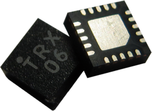
24 GHz Transceivers
| Front End | Status of IC | Package | Antenna Solutions | Evaluation / Sensor |
|
Single Channel Transceiver / Receiver |
|
|
||
|
Multi Channel Transceiver
|
|
|
(1) Qualified after JEDEC; MSL
Contents
1 TRX_024_006
The IC is an integrated transceiver circuit for the 24-GHz ISM band in the frequency range 24.0 GHz – 24.25 GHz. It includes a low-noise amplifier (LNA) with gain control, quadrature mixers, a poly-phase filter, a voltage controlled oscillator with band switching, and a divide-by-32 circuit. The receiver can be powered down if PWR_RX pin is supplied with 0 V. The gain of the receiver can be digitally controlled by Vct pin: Vct = 3.3 V sets the receiver in high gain mode, Vct = 0 V sets the receiver in low gain mode. The output power of the transmitter can be controlled by the pwr1 input. The IC is fabricated in SiGe BiCMOS technology[1] using the bipolar part and the CMOS part.
Beside the TRXˍ024ˍ006, an IC variant with a divider division ratio of 1:8 is available as TRX_024_007.
The TRXˍ024ˍ006 can be used in wireless communication systems and in radar systems for the ISM band from 24.0 GHz to 24.25 GHz and for UWB applications between 23 GHz and 26 GHz.
2 TRX_024_007
The IC is an integrated transceiver circuit for the 24-GHz ISM band in the frequency range 24.0 GHz – 24.25 GHz. It includes a low-noise amplifier (LNA) with gain control, quadrature mixers, a poly-phase filter, a voltage controlled oscillator with band switching, and a divide-by-8 circuit. The receiver can be powered down if PWR_RX pin is supplied with 0 V. The gain of the receiver can be digitally controlled by Vct pin: Vct = 3.3 V sets the receiver in high gain mode, Vct = 0 V sets the receiver in low gain mode. The output power of the transmitter can be controlled by the pwr1 input. The IC is fabricated in SiGe BiCMOS[2] technology by using the bipolar part and the CMOS part.
Beside the TRXˍ024ˍ007, an IC variant with a divider division ratio of 1:32 is available as TRXˍ024ˍ006.
The TRXˍ024ˍ007 can be used in in radar systems and wireless communication systems for the ISM band from 24.0 GHz to 24.25 GHz and for UWB applications between 23 GHz and 26 GHz.
3 FAQ: TRX_024_00*
What is the difference between TRX_024_006 and TRX_024_007?
- The only difference is the divider ratio of 1/8 with the TRX_024_007 and 1/32 with the TRX_024_006.
What does the TX-EN-Pin do?
- The TX_EN pin is an enable pin for the on-chip VCO, buffer and PA. It is not possible to switch off the signal at the TXout pin and to let the VCO and divider run.
Why are there frequency variations in the VCO?
- Due to technology tolerances the VCO has frequency variations. Unfortunately we cannot do much about it. That is why we implemented a wide tuning range in TRX_024_006 and TRX_024_007, which enables the ICs to operate in the required ISM band. It is required to implement a mechanism for frequency stabilization on the system (sensor) level to guarantee operation in ISM band. There are different ways to achieve this. One of the most common is to use a PLL.
- It is possible to perform screening test and select components with smallest (defined) variations in parameters. However, this requires the development of new hardware and software for production tests, which is costly. If such an option is interesting for you, please provide us with the quantities you commit to purchase and we will estimate the cost of the device tested under special conditions.
How can I calculate the phase noise?
- We provide phase noise measurements starting from 30 kHz offset from the carrier due to limitations in our measurement setup. Our TRX circuits are commonly used with a PLL and in this case the phase noise of the VCO at low offsets from the carrier is suppressed by loop filters and quartz oscillators. You can extrapolate the phase noise by assuming that it decreases by 20 dB per decade from carrier (it starts to saturate in the range of approx 10 MHz offset).
How quickly can I switch between the different bands on the transceiver?
- We have never checked how fast one can switch the bands because the circuit normally operates in only one band (ISM bandwidth). The band switching is implemented to compensate for technology, temperature or supply variations. The switching time is not relevant in such cases.
What is the size?
- 3 mm x 3 mm
What is the weight ?
- 0,235 g
What is the power consumption?
- All of our ICs have a low power consumption. The power consumption of the TRX_024_006/007 is 300 mW in continuous operating mode. A further, significant reduction can be achieved with an operation in low duty cycle.
What is the output impedance of the transmitter?
- The output impedance of the transmitter is 50 Ohm.
Can you provide S-parameter file?
- We have no S-parameters measurements for TX. It is difficult to measure large signal S-parameters of TX with an integrated oscillator. The TX parameters in our datasheets were measured for 50 Ohm load at TX output.
What are the reading rates and the aperture angle?
- These parameters depend on the radar application and the radar system for which the chip is used.
What is the maximum range?
- Depending on the antenna used, the chip is good for several hundreds of meters.
Are there any recommendations if I would like to use horn antennas for TX and RX?
- We unfortunately cannot give any recommendation for antennas because we do not have enough experience (we design only MMICs). The choice of antennas strongly depends on the application. If you consider using horn antennas (which normally have rather high gain) keep in mind the linearity of the receiver.
