120 GHz Transceivers
| Front End | Status of IC | Package | Antenna Solutions | Evaluation / Sensor |
|
Single Channel Transceiver |
|
|
||
|
Single Channel Transceiver |
|
|
||
|
Ultra Wideband Single Channel Transceiver
|
|
|
||
|
Multi Channel Transceiver
|
|
|
|
SiRad Easy® (under development) |
(1) Qualified after JEDEC; MSL
(2) Under investigation
(3) Incl. lens (Si / 3D-printed)
(4) Patented assembly solution
(5) In silicon, completely moulded
Contents
1 TRX_120_001
The RFE is an integrated transceiver circuit for the 122-GHz ISM band with antennas in QFN 8x8 package. It includes a low-noise amplifier (LNA), quadrature mixers, a poly-phase filter, a voltage controlled oscillator, divide-by-32 outputs and transmit and receive antennas. The RF signal from the oscillator is directed to the RX path via buffer circuits. The RX signal is amplified by the LNA and converted to the baseband by two mixers with quadrature local oscillator (LO). The 120-GHz LO has four analog tuning inputs with different tuning ranges and tuning slopes. The tuning inputs can be combined to obtain a wide frequency tuning range. The analog tuning inputs together with integrated frequency divider and external fractional-N PLL can be used for frequency modulated continuous wave (FMCW) radar operation. With fixed oscillator frequency it can be used in continuous wave (CW) mode. Other modulation schemes are possible as well by utilizing analog tuning inputs. The IC is fabricated in SG13S SiGe BiCMOS technology [1].
The main application field of the 120-GHz transceiver radar frontend is in short range radar systems with a range up to some 10 meters. By using dielectric lenses, the range can be increased considerably. The RFE can be used in FMCW mode as well as in CW mode. Although the chip is intended for use in the ISM band 122 GHz - 123 GHz, it is also possible to extend the bandwidth to the full tuning range of 7 GHz.
2 TRX_120_002
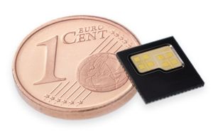
The radar-front end (RFE) is an integrated transceiver circuit for the 120 GHz ISM band with antennas on chip in a QFN 5x5 package. It includes a low-noise amplifier (LNA), quadrature mixers, poly-phase filter, voltage controlled oscillator with digital band switching, divide-by-32 outputs, and transmit and receive antennas. The RF-signal from oscillator is directed to RX path via buffer circuits. The RX signal is amplified by a LNA and converted to baseband in two mixers with quadrature LO. The 120 GHz oscillator has three analog coarse tuning inputs and one analog fine tuning input. The tuning inputs can be combined to obtain large tuning range and large bandwidth. The analog tuning inputs together with integrated frequency divider and external fractional-N PLL can be used for frequency modulated continuous wave (FMCW) radar operation. With fixed oscillator frequency it can be used in continuous wave (CW) mode. Other modulation schemes are possible as well by utilizing analog tuning inputs. The IC is fabricated in IHP SG13S SiGe BiCMOS technology [2].
Main application field of the 120 GHz transceiver RFE is in short range radar systems. With the use of dielectric lenses, the range can be increased considerably. The RFE can be used in FMCW mode as well in CW-mode. Although the chip is intended for use in ISM band 122 GHz - 123 GHz, it is also possible to extend bandwidth to the full tuning range of almost 7 GHz.
3 FAQ: TRX_120_00*
What is the difference between the two ICs?
- Both chips include send and receive antennas in a standard QFN package. The main difference lies in the antenna designs. While the TRX_120_001 uses tiny patch antennas on a separate "PCB" within the IC's package, the TRA_120_002 has its dipole antennas already included on the chip die. Therefore the packages are different in size and beam characteristics differ.
What is the minimum range or is there a blind spot?
- The minimum range is dependent on the selected bandwidth. 1 GHz bandwidth works from about 30 cm, 6 GHz works from about 7 cm.
What is the covered area / the field of view of the TRX_120_001?
- The area covered by the radar over distance is dependent on the field of view of the sensor. Without lens the sensor has an opening angle of +/-30 degrees (-6dB), with lens this can be narrowed to about +/- 2 degrees.
What is the field of view of the TRX_120_002?
- The beam of the TRA_120_002 has an angle of nearly 180°.
Can something be detected below the minimum range?
- Going below the bandwidth-dictated minimum range leads to an increased DC-offset in the FFT output. It could be used to detect "something is nearby" but this is very application-specific.
What is the resolution of the chips?
- We define the resolution as the ability to separate two objects in range. The resolution is only dependent on the selected bandwidth. With 1 GHz bandwidth the resolution is 15 cm, 6 GHz equals to 2,5 cm resolution. In practice, target recognition works from twice the resolution.
What is the maximum range?
- The maximum range of our 120 GHz chips is always dependent on the target. Usually we can reach about 10 m without a lens and about 25 – 30 m with a lens.
Can I create a continous sweep of 6 GHz bandwidth?
- The radar frontends can be used in discrete channel mode by selecting channels via the coarse tuning inputs. Since the tuning inputs are just varactor diodes, it is also possible to connect all tuning inputs together to get the full bandwidth of 6 GHz.
What is the size?
- The TRX_120_001 is produced in a 8 mm x 8 mm QFN package. The TRA_120_002 comes in a 5 mm x 5 mm QFN package.
